Injection molding encapsulation mould with positioning fixture mechanisms

A technology for positioning fixtures and injection molding encapsulation, which is applied in the field of fixture mechanisms, can solve the problems of inconvenient encapsulation, impossibility of injection molding, easy movement or movement, etc., and achieve the effects of improving production efficiency, convenient installation and removal, and convenient operation

Active Publication Date: 2014-04-16
PERLMAN ELECTRICAL KUSN
View PDF7 Cites 0 Cited by
  • Summary
  • Abstract
  • Description
  • Claims
  • Application Information

AI Technical Summary

Problems solved by technology

[0003] However, the injection mold manipulator automation device is an indispensable auxiliary equipment in the working process of the injection molding machine. It is widely used in the injection molding industry and has a wealth of technical content. However, in actual use, for special products and specific injection molds , the manipulator cannot achieve the required effect, especially when producing round products with rubberized products by injection molding. Since the wrapped round products need to be placed in the mold cavity for injection molding, during the insertion process, because the products are round, It is easy to move or move so that it cannot be accurately placed in the corresponding position, and the root of the injection mold is encapsulated, making it impossible to perform injection molding, resulting in difficulty in encapsulating the root of the product or inconvenient encapsulation, and low efficiency. In this case , there is an urgent need for a fixture mechanism that can cooperate with the manipulator to fix the round product to be glued, and is convenient for safe and accurate glueing at the root of the product and easy and quick demoulding

Method used


Image

  • Injection molding encapsulation mould with positioning fixture mechanisms
  • Injection molding encapsulation mould with positioning fixture mechanisms

Examples


Embodiment Construction

[0016] In order to make the technical means, creative features, goals and effects achieved by the present invention easy to understand, the present invention will be further described below in conjunction with specific embodiments.

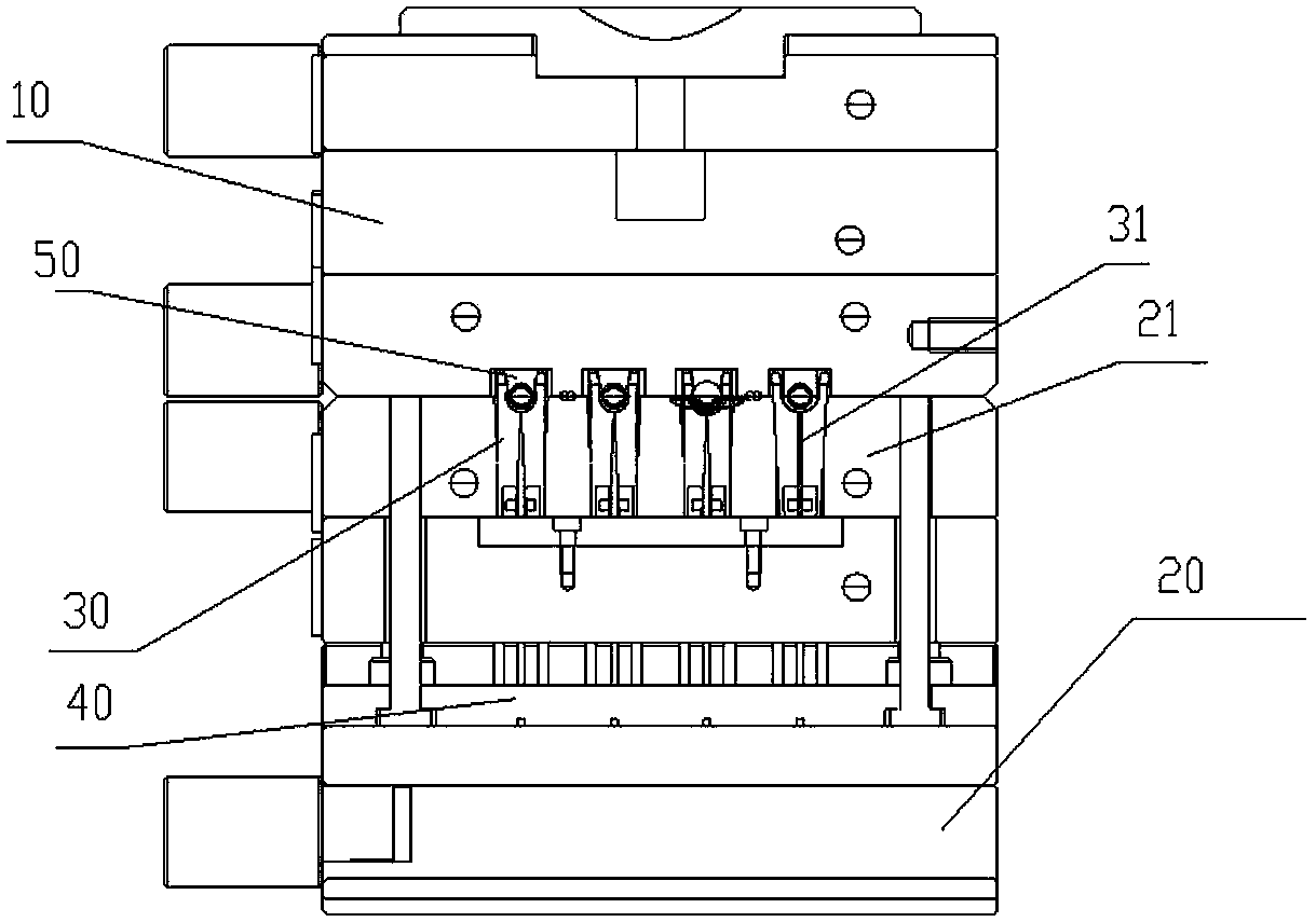
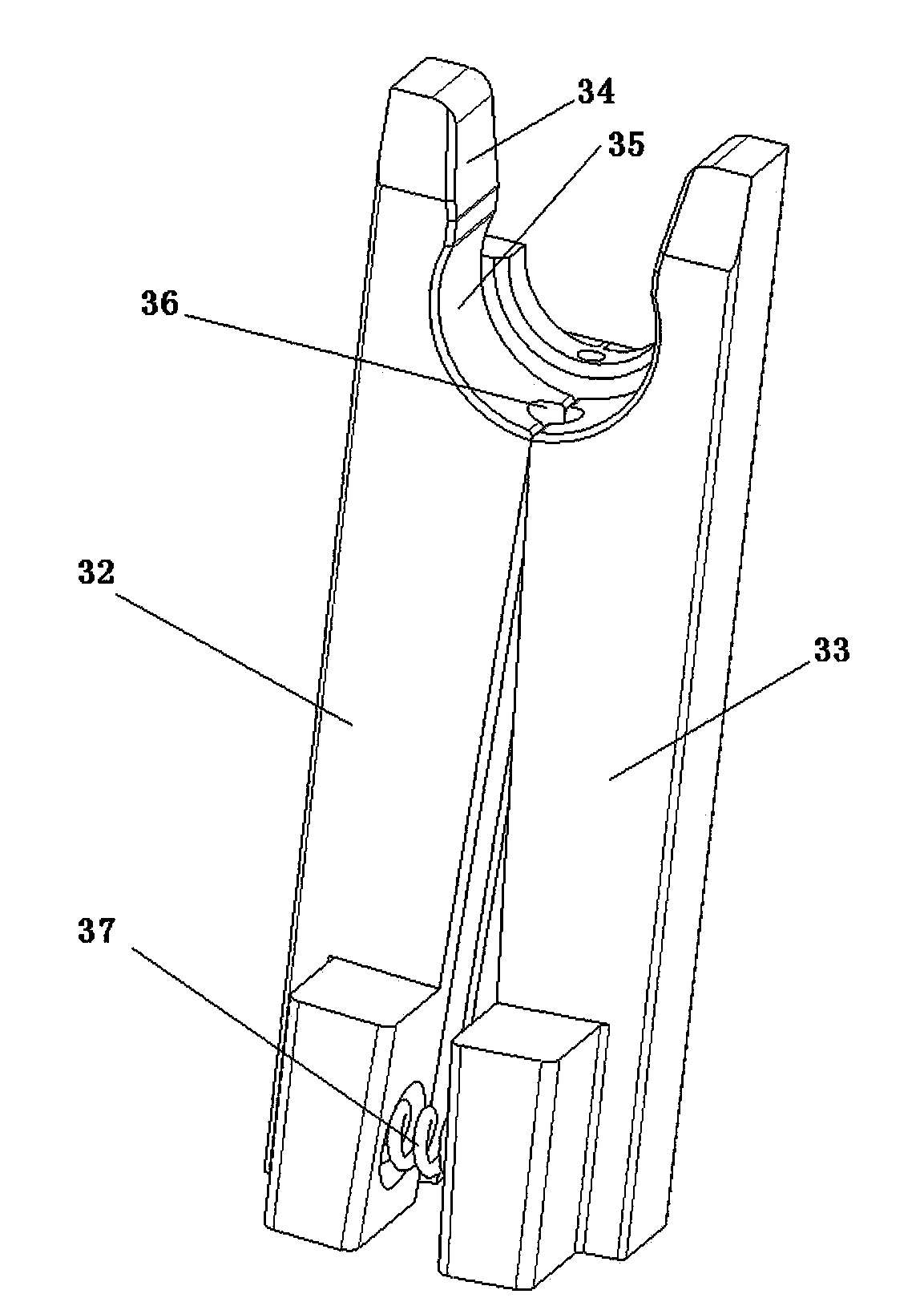
[0017] see figure 1 and figure 2 , an injection overmolding mold with a positioning fixture mechanism of the present invention, which includes a fixed mold 10, a movable mold 20, a mold core 21 arranged on the movable mold 20, and an ejection mechanism arranged below the mold core 21. A plurality of positioning fixtures for fixing round workpieces to be coated are installed in the mold core 21, and a positioning fixture mechanism 30 is also arranged on the positioning fixture mechanism. The lower end of the clamp body is used to urge the clamp body to clamp the elastic device of the circular workpiece to be glued. In the clamp body, there is also an ejector rod 31 for ejecting the workpiece. The ejector rod 31 is connected to the ejector mechani...


PUM


Abstract

The invention relates to an injection molding encapsulation mould with positioning fixture mechanisms. The mould comprises a stationary mould, a movable mould, a mould core which is arranged on the movable mould, and an ejector mechanism which is arranged below the mould core, wherein a plurality of positioning fixture mechanisms which are used for fixing circular workpieces to be encapsulated are arranged on the mould core; each positioning fixture mechanism comprises a fixture body, a workpiece fixture groove which is formed at the upper end of the fixture body, and an elastic device which is arranged at the lower end of the fixture body and is used for urging the fixture body to firmly clamp a circular workpiece to be encapsulated; an ejector rod which is used for ejecting the workpiece is arranged in the fixture body; and the ejector rod is connected with the ejector mechanism. By arranging the positioning fixture mechanisms, the mould can be conveniently used by the fixed and implanted circular workpieces, has the effects of assembling and disassembling conveniently and quickly, and can be conveniently matched with a manipulator for automatic installation; the mould can eject the circular workpieces which are perfectly encapsulated by arranging the ejector rods; and the mould can be conveniently and quickly operated, realizes the encapsulation of roots, namely bottoms of circular products, is safe and reliable, and greatly improves production efficiency.

Description

technical field [0001] The invention relates to a clamp mechanism, in particular to an injection molding overmolding mold with a positioning clamp mechanism. Background technique [0002] As we all know, injection mold is a kind of mold that is widely used in the current industrial production process. It is mainly composed of fixed mold, moving mold and ejection mechanism. The ejection mechanism is often on the moving mold. When the movable mold moves back to a certain position, the push plate on the injection molding machine pushes the ejector mechanism of the mold to eject the product. For some side concave products, it is often done by setting an inclined ejector mechanism. To open the mold, corresponding molding features should be set on the inclined top. After the product is formed, the inclined top is pushed down by the injection molding machine to eject the formed product, and the mold opening is completed. [0003] However, the injection mold manipulator automation ...

Claims


Application Information

Patent Timeline
Patent Type & Authority Patents(China)
IPC IPC(8): B29C45/26B29C45/40
Inventor 吴鞘
Owner PERLMAN ELECTRICAL KUSN
Why Eureka
Try Eureka