Electronic cam control device and electronic cam curve generation method

A technology of electronic cam and control device, which is applied in the direction of electric controller, electric program control, non-electric variable control, etc. It can solve the problems of slave shaft vibration, slave shaft servo motor position cannot be completely followed, impact, etc., and achieve acceleration suppression Effect

Active Publication Date: 2014-02-05
MITSUBISHI ELECTRIC CORP
View PDF9 Cites 24 Cited by
  • Summary
  • Abstract
  • Description
  • Claims
  • Application Information

AI Technical Summary

Problems solved by technology

In this case, the following problems arise: the position of the slave axis servo motor cannot completely follow the position indicated by the electronic cam curve, or, vibration or shock is generated in the slave axis

Method used


Image

  • Electronic cam control device and electronic cam curve generation method
  • Electronic cam control device and electronic cam curve generation method
  • Electronic cam control device and electronic cam curve generation method

Examples


Embodiment approach 1

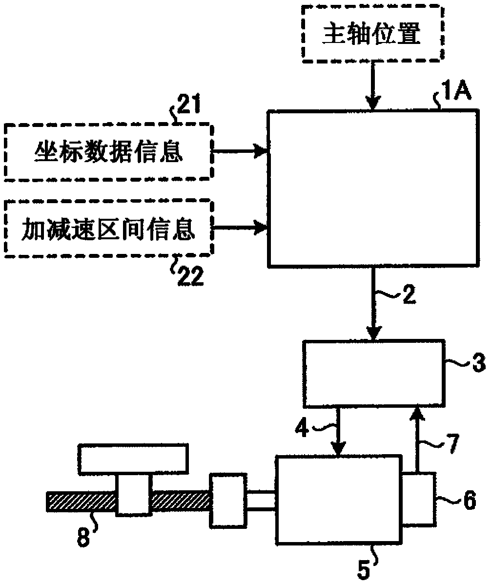
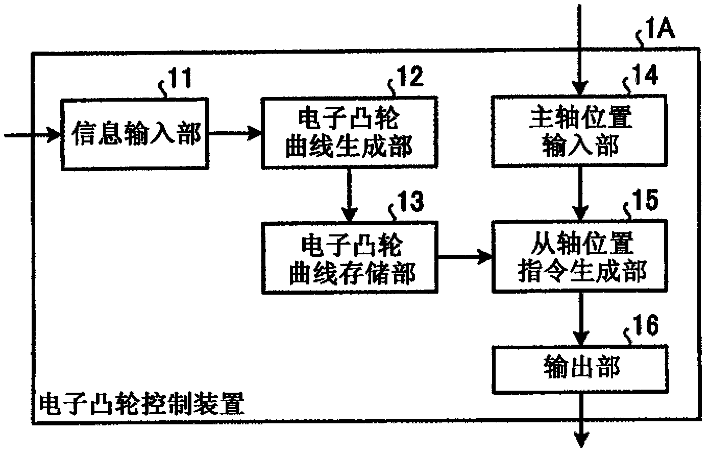
[0028] figure 1 It is a figure which shows the structure of the electronic cam system concerning Embodiment 1. The electronic cam system includes an electronic cam control device 1A, a servo amplifier 3 , a servo motor 5 , an encoder 6 , and a load mechanism 8 .

[0029] The electronic cam control device 1A is a device that generates an electronic cam profile and controls the servo amplifier 3 , the servo motor 5 , and the load machine 8 using the generated electronic cam profile. In the electronic cam system, by controlling the servo amplifier 3 with the electronic cam control device 1A, the servo amplifier 3 controls the servo motor 5 and thereby controls the load machine 8 .

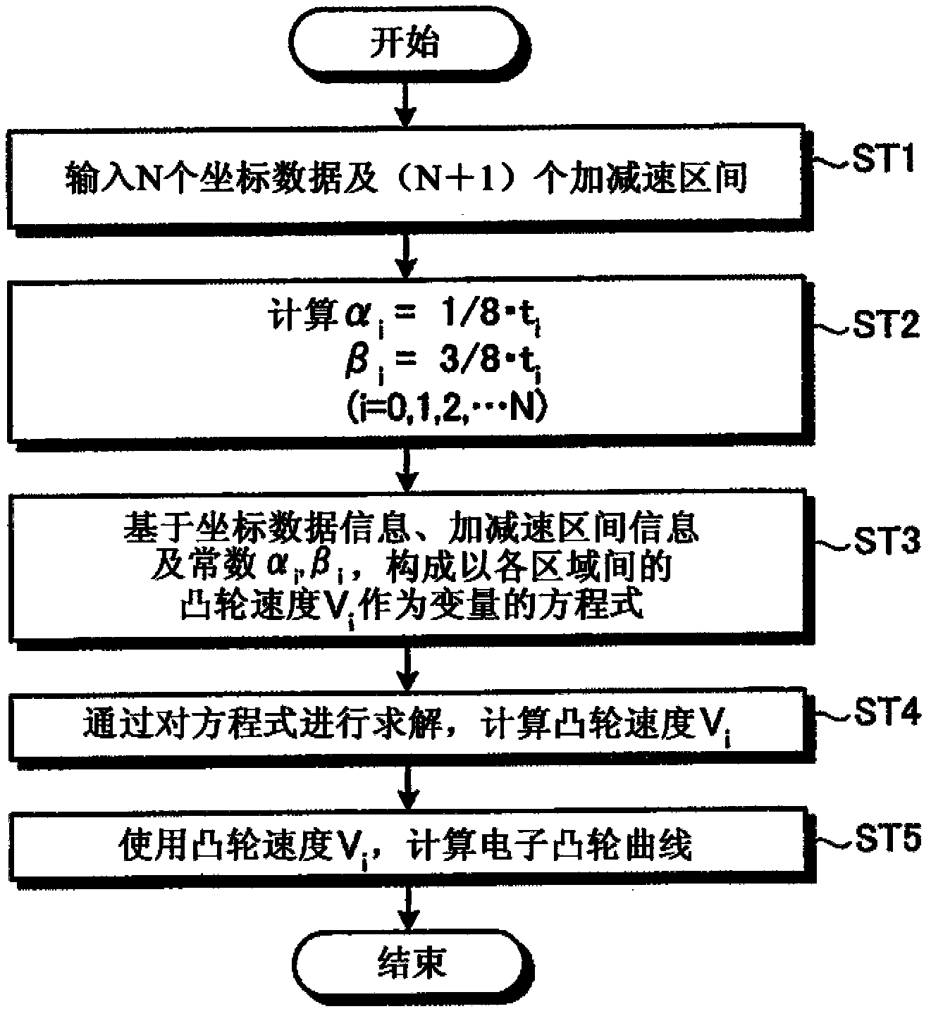
[0030] The electronic cam control device 1A generates an electronic cam curve based on coordinate data information 21 and acceleration / deceleration interval information 22 input by the user in advance, wherein the coordinate data information 21 specifies the positional relationship between the master...

Embodiment approach 2

[0166] Next, use Figure 7 and Figure 8Embodiment 2 of the present invention will be described. In the electronic cam system according to Embodiment 1, in addition to the designated N coordinates, an electronic cam curve is obtained using (N+1) acceleration / deceleration intervals. The electronic cam system of this embodiment also obtains an electronic cam curve having the same properties as that of Embodiment 1, but instead of (N+1) acceleration / deceleration intervals, one parameter is used. Moreover, the electronic cam system automatically determines (N+1) acceleration and deceleration intervals according to a parameter, and then obtains the electronic cam curve.

[0167] Figure 7 It is a figure which shows the structure of the electronic cam system concerning Embodiment 2. for Figure 7 The realization and figure 1 The constituent elements of the electronic cam system according to Embodiment 1 shown with the same functions are denoted by the same reference numerals a...

Embodiment approach 3

[0218] Next, use Figure 9 to Figure 11 , Embodiment 3 of the present invention will be described. The electronic cam system of Embodiments 1 and 2 generates the following electronic cam curve, the waveform of which is the cam speed obtained by differentiating the position of the slave shaft with respect to the position of the main shaft, and the constant cam speed V in the adjacent area i , V i+1 between linear acceleration / deceleration. The electronic cam system of the present embodiment generates an electronic cam curve by connecting constant cam speeds in adjacent regions in an arbitrary curve that monotonically increases or decreases monotonically. In the present embodiment, an example will be described in which an electronic cam curve is generated by connecting constant cam speeds in adjacent regions in a continuous acceleration / deceleration curve. The electronic cam system of this embodiment generates, for example, an electronic cam curve in which the cam speed accel...


PUM


Abstract

An electronic cam control device is provided with an electronic cam curve generation unit which generates an electronic cam curve so as to pass through a plurality of designated coordinates that define a relationship between major axis positions and minor axis positions, and an output unit which outputs minor axis positions corresponding to the major axis positions as position instructions to an external device according to the electronic cam curve. The electronic cam curve generation unit generates an electronic cam curve in which a cam velocity waveform, in which the electronic cam curve has been differentiated with regard to the major axis positions, has intervals with a uniform cam velocity for each area that is between designated coordinates, and has monotonic acceleration/deceleration intervals connecting together intervals with a uniform cam velocity by accelerating or decelerating while monotonically increasing or monotonically decreasing between neighboring areas.

Description

technical field [0001] The present invention relates to an electronic cam control device and an electronic cam curve generation method that generate an electronic cam curve from the relationship between the position of the main axis and the position where the slave axis should be when it moves corresponding to the position of the main axis. Background technique [0002] The electronic cam control device is a device that does not install a mechanical cam mechanism, but outputs the position where the slave axis should be when it moves corresponding to the position of the master axis based on the electronic cam curve set by software. Here, the position of the main shaft is, for example, the position of a servo motor of another axis, or the position of a synchronous encoder provided on a certain rotary axis, or the like. [0003] For example, an electronic cam control device is used in a rotary knife device, which drives a rotary knife synchronously with the movement of the pape...

Claims


Application Information

Patent Timeline
Patent Type & Authority Applications(China)
IPC IPC(8): G05D3/00
CPCF16H25/08G05B19/4083G05B11/36G05B2219/34343G05B19/416G05D3/12
Inventor 上田浩一郎丸下贵弘水野公博
Owner MITSUBISHI ELECTRIC CORP
Why Eureka
Try Eureka