Check patentability & draft patents in minutes with Patsnap Eureka AI!

cooling device

A cooling device and ventilation device technology, applied in cooling/ventilation/heating renovation, electrical components, electrical equipment structural parts, etc., can solve problems such as large installation space, and achieve the effect of high cooling power

Active Publication Date: 2016-03-30
RITTALWERK RUDOLF LOH GMBH & CO KG
View PDF5 Cites 0 Cited by
  • Summary
  • Abstract
  • Description
  • Claims
  • Application Information

AI Technical Summary

Problems solved by technology

Known air conditioning devices have a relatively large construction width and therefore require a corresponding installation space

Method used


Image

  • cooling device
  • cooling device

Examples


Embodiment Construction

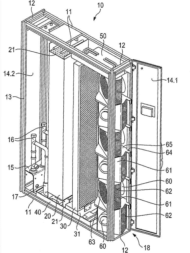
[0024] figure 1 The cooling device is shown with a frame 10 surrounding the receiving area. The frame 10 consists of eight horizontal frame elements and four vertical frame elements 11 , 12 , 13 . Here, two horizontal frame parts 11 extending in the depth direction of the cooling device and two horizontal frame parts 12 extending in the width direction of the cooling device form a bottom frame and a top frame. The bottom frame is connected to the top frame via four vertical frame pieces 13 in the corner regions of the frame 10 . The receiving area can be closed at the front with a cover 14.1 and at the rear with a cover 14.2. In this case, the covers 14.1, 14.2 are preferably fastened in a hinged manner, so that they form doors that facilitate access to the receiving area.

[0025] In the region of the rear side of the frame 10 the support 15 is stably fastened to the bottom frame and to the two vertical frame parts 13 . The bracket 15 carries a connection attachment 16 , ...


PUM


Abstract

The invention relates to a cooling device comprising a receptacle region, in which a heat exchanger and at least one fan unit are arranged, wherein the fan unit is or comprises a radial fan and wherein the radial fan generates an air flow having a main flow direction through the heat exchanger. In order to produce cooling devices having simultaneously a high cooling capacity and a small structural width, the invention provides for the radial fan to be arranged behind the heat exchanger in the flow direction and for the axis of rotation of the radial fan to be at an angle of < 90° with respect to the main flow direction.

Description

technical field [0001] The invention relates to a cooling device with a receiving area in which a heat exchanger and at least one ventilation unit are arranged, wherein the ventilation unit is a radial ventilation unit or the ventilation unit has such a A radial ventilation device, and wherein the radial ventilation device generates an air flow with a main flow direction through the heat exchanger. Background technique [0002] A cooling device is known from WO 2009 / 141610 A1 for cooling electronic components arranged in racks or switch cabinets. In this case, the cooling device is integrated into the rows of racks or switch cabinets, which in the data center separate the cold aisles from the hot aisles. The cooling device receives hot air from the hot aisle, cools the hot air and then delivers it conditioned into the cold aisle. In order to generate the air flow, a fan impeller is installed in the air conditioner, which draws in the air to be cooled. The cooled air is bl...

Claims


Application Information

Patent Timeline
Patent Type & Authority Patents(China)
IPC IPC(8): H05K7/20
CPCH05K7/20745
Inventor M·德里希D·黑曼M·尼科莱J·扎策尔D·泰斯
Owner RITTALWERK RUDOLF LOH GMBH & CO KG
Features
  • R&D
  • Intellectual Property
  • Life Sciences
  • Materials
  • Tech Scout
  • Unparalleled Data Quality
  • Higher Quality Content
  • 60% Fewer Hallucinations
Learn More