

Building fastener bolt
A technology of bolts and fasteners, applied in the field of fasteners for construction, can solve the problems of bolts sliding out of bayonet, steel pipes sliding out, etc.
- Summary
- Abstract
- Description
- Claims
- Application Information
AI Technical Summary
Problems solved by technology
Method used
Image

Examples
Embodiment Construction
[0008] Below in conjunction with accompanying drawing and specific embodiment the present invention will be described in further detail:
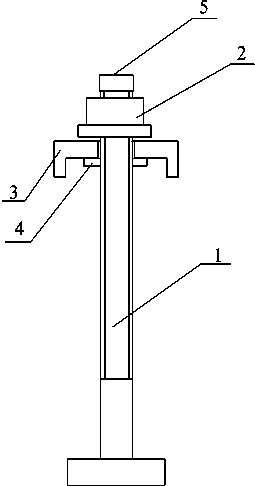
[0009] Such as figure 1 Shown: the embodiment of the present invention provides a bolt for building fasteners, including a T-shaped bolt 1, a U-shaped clip 3 and a nut 2 connected to the T-shaped bolt 1, and the U-shaped clip 3 is restricted on the T-shaped bolt 1 by the nut 2 , the U-shaped card 3 and the T-bolt 1 slide relatively, and the contact surface of the U-shaped card 3 and the fastener is provided with a matching convex surface 4 .
[0010] The fasteners fixed with this T-shaped bolt 1 need to meet the requirements that there are card edges on both sides of the bayonet of the clip. Through the limit of the card edge, even if the T-bolt is not fastened, the T-bolt is firmly restricted in the bayonet, which prevents the T-bolt from falling out, realizes one-time installation, and makes the installation safer. The threaded end of t...
PUM
 Abstract
Description
Claims
Application Information