Round bearing wrench for numerical control tools

A bearing wrench, circular technology

Inactive Publication Date: 2018-03-06
常州巨丰精密工具制造有限公司
View PDF0 Cites 0 Cited by
  • Summary
  • Abstract
  • Description
  • Claims
  • Application Information

AI Technical Summary

Problems solved by technology

[0003] The traditional bearing wrench has a single structure, and each wrench corresponds to a specific model, which cannot be applied to multiple models. When installing different types of bearings, it is necessary to change the corresponding model, which is inconvenient in actual use. The applicability is limited and the efficiency is not high

Method used


Image

  • Round bearing wrench for numerical control tools
  • Round bearing wrench for numerical control tools
  • Round bearing wrench for numerical control tools

Examples


Embodiment 1

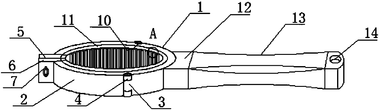
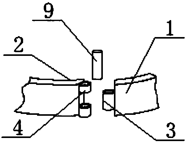
[0023] see figure 1 with figure 2 As shown, a circular bearing wrench for numerically controlled cutting tools includes a fixed ring 1, a movable ring 2 and a clip 10, a connecting buckle 3 is arranged on both sides of the fixed ring 1, a connecting ring 4 is arranged on one side of the movable ring 2, and the connecting buckle 3 and the The connecting ring 4 cooperates with each other, and the connecting buckle 3 and the connecting ring 4 are connected by the pivot pin 9, so that the fixed ring 1 and the movable ring 2 can be flexibly connected, so that the movable ring 2 can freely expand the angle of one end in the horizontal direction, and the movable ring 2 One side is respectively connected with the first connecting block 5 and the second connecting block 6, the first connecting block 5 is connected with the connecting bolt 8, the connecting bolt 8 is connected with the knob nut 7, and the connecting bolt 8 runs through the first connecting block 5 and the second connec...

Embodiment 2

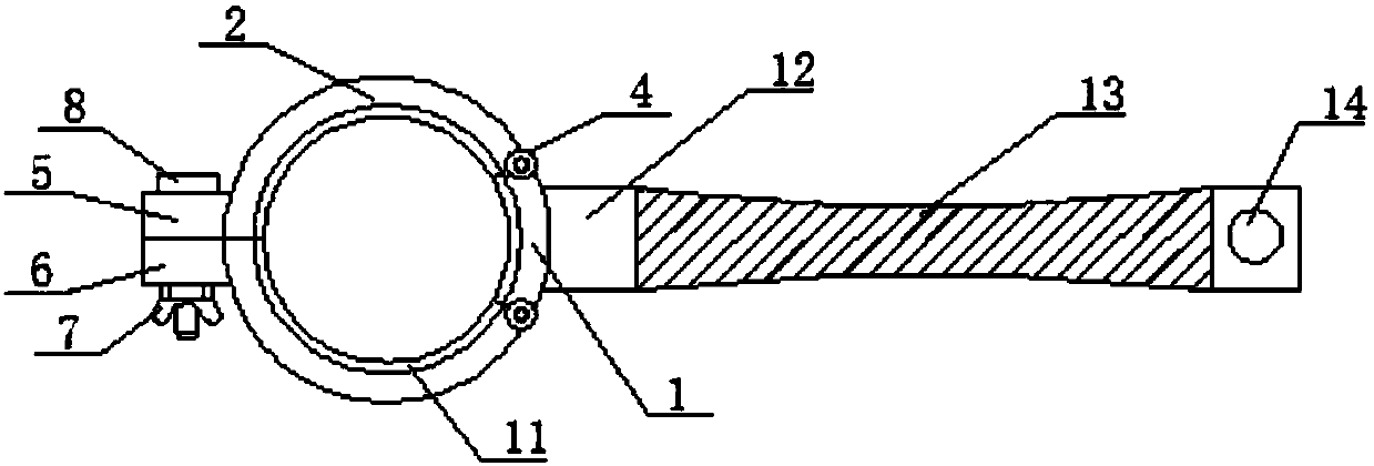
[0025] In addition, refer to Figure 2-Figure 6 , based on the above embodiment, let the fixed ring 1 and the movable ring 2 on both sides form a circular wrench, the fixed ring 1 and the movable ring 2 on both sides are movably connected, and the movable ring 2 can rotate freely in the horizontal direction, The device can be conveniently clamped to the bearing, and can be applied to various types of bearings. The connecting buckle 3 on both sides of the fixed ring 1 is set in the middle position, and the side of the movable ring 2 is provided with a symmetrical connecting ring 4. The groove formed by the connecting ring 4 Cooperate with the connecting buckle 3, the connecting buckle 3 and the connecting ring 4 are all provided with holes matched with the shaft pin 9, so that the fixed ring 1 and the movable ring 2 can rotate freely and are firmly connected, and the first connection on the movable ring 2 The block 5 and the second connecting block 6 are all provided with holes...


PUM


Abstract

The invention discloses a circular bearing wrench for numerically controlled cutting tools, which comprises a fixed ring, a movable ring, a connecting buckle, a connecting ring, a first connecting block, a second connecting block, a knob nut, a connecting bolt, a pivot pin, a fastener, a fixing loop, handle, case and hanging hole. The present invention is provided with a fixed ring and a movable ring, the movable ring and the fixed ring are movably connected, the movable ring can be freely opened at a certain angle in the horizontal direction, and the diameter of the inner ring of the device can be changed within a certain range. The bearing saves the time of replacing the wrench. There are clamps in the fixed ring and the movable ring, which can be fastened clockwise and counterclockwise. It can be satisfied in different fastening directions, so that the device has a wider range of application. Both the upper end surface and the lower end surface of the bearing are provided with fixing rings, which can effectively prevent the bearing from falling during the installation process while fastening the bearing, making the bearing more safe and reliable during the installation process.

Description

technical field [0001] The invention relates to a bearing wrench, in particular to a circular bearing wrench for numerically controlled cutting tools, which belongs to the field of mechanical auxiliary equipment. Background technique [0002] In the field of equipment processing, bearing wrenches of various types and specifications are needed to help the fastening of bearings. The frequency of use of bearing wrenches is very high, which can improve the installation efficiency of bearings and save the installation time of devices. [0003] The traditional bearing wrench has a single structure, and each wrench corresponds to a specific model, which cannot be applied to multiple models. When installing different types of bearings, it is necessary to change the corresponding model, which is inconvenient in actual use. Applicability is limited, and the use efficiency is not high. Contents of the invention [0004] The object of the present invention is to provide a circular be...

Claims


Application Information

Patent Timeline
Patent Type & Authority Applications(China)
IPC IPC(8): B25B13/48B25B13/10
Inventor 殷玲燕
Owner 常州巨丰精密工具制造有限公司
Why Eureka
Try Eureka