

Method for mounting ship three-main-engine three-airscrew main frame shafting
A technology for propellers and main shafts, applied to shaft frames, hulls, ship parts, etc.
- Summary
- Abstract
- Description
- Claims
- Application Information
AI Technical Summary
Problems solved by technology
Method used
Image

Examples
specific Embodiment approach
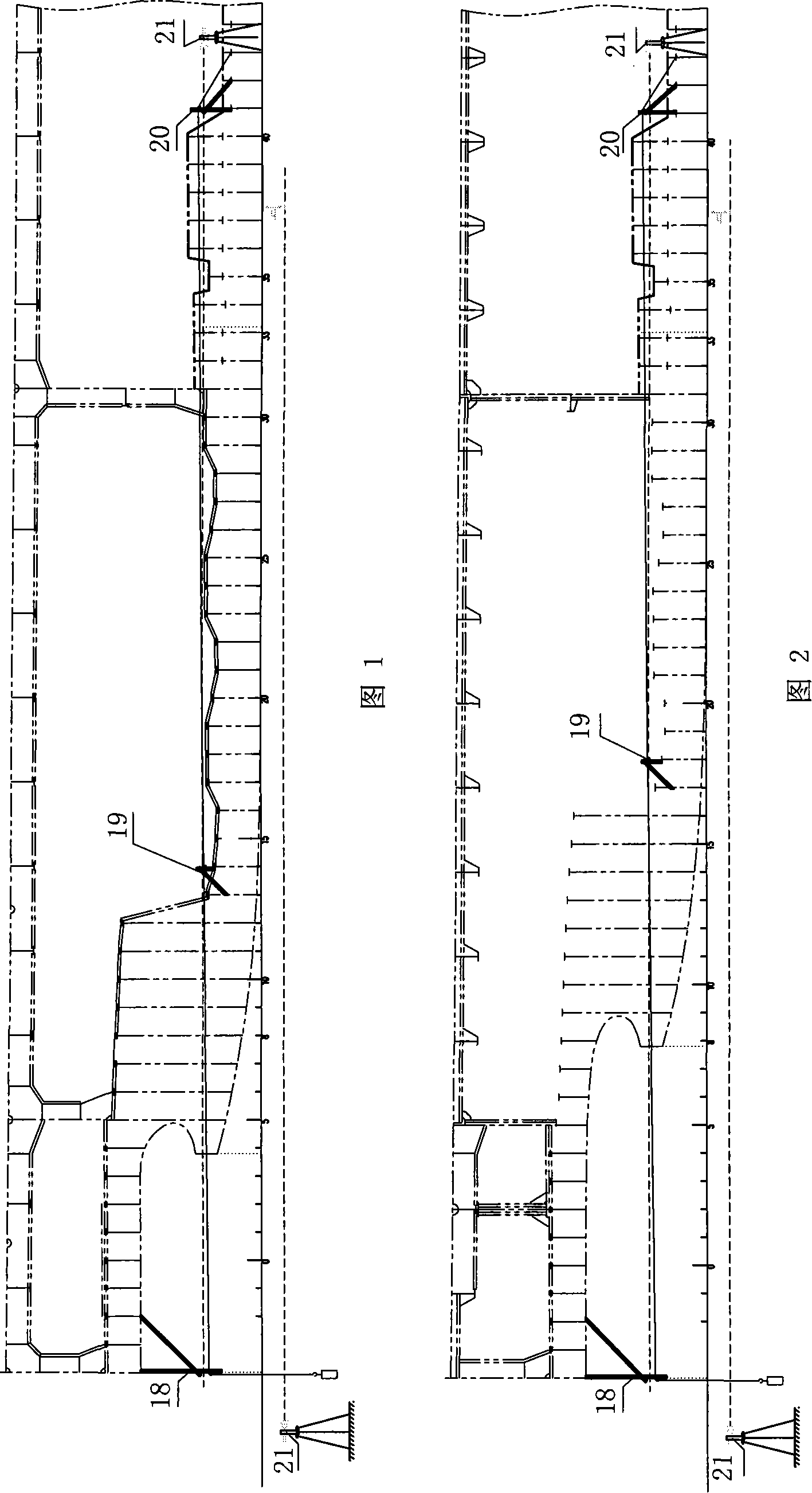
[0019] 1 Measurement of centerline of ship shafting.
[0020] 1.1 Overview
[0021] The ship has 3 shaft systems, namely the left and right side shaft systems and the midship shaft system. The left and right side side shafts are respectively 5785mm away from the midship, the tail of the side axis is 970mm above the baseline at #8-100 (3900mm towards the bow of #0), and the height of the bow is 970mm above the baseline at #33+100 (16600mm towards the bow of #0) 1100mm, the inclination angle between the axis and the baseline is about 0.7574°; the central axis is located in the midship, the longitudinal axis coincides with the midship, the tail of the central axis is 970mm above the baseline at #4 100 (1900mm from #0 to the bow), and the bow is at #33(# 0 to the bow (16600mm) is 1100mm above the baseline, and the inclination angle between the axis and the baseline is about 0.5961°.
[0022] 1.2 Basic requirements for centerline of ship shafting
[0023] 1.2.1. The deviation be...
PUM
 Abstract
Description
Claims
Application Information