Spherical Display and Control Device

a control device and display technology, applied in the direction of cathode-ray tube indicators, instruments, electric digital data processing, etc., can solve the problems of increasing the complexity of computing and data representation, awkward 3d navigation use of devices, and reducing the comfort of users, so as to facilitate two-way communication, facilitate drill-down and selection, and increase the comfort of users

Inactive Publication Date: 2007-10-25
DANIEL SIMON +2
View PDF24 Cites 129 Cited by
  • Summary
  • Abstract
  • Description
  • Claims
  • Application Information

AI Technical Summary

Benefits of technology

[0023] Of particular benefit is where the device is used as an information navigator, to say show primary category organization of say six classes of information, and enable drill down through selection of a class to show ‘fractal-like’ sub-classes arranged around the sphere, and enable rapid drill-down and selection. Such a spherical representation and selection could be applied to manage folders of information, or to manage links (such as web favourites), so that a vast amount of information was easily accessible visually and by touch action. This is of increasing importance as modern consumers rely on managing vast quantities of information, much of which is external links or access points. Said device would therefore act as an information ball providing the user with a dynamic ‘crystal ball’ access device to the web, their personal data storage or to external data banks. Said information navigator could be mirrored wirelessly with a software animated 3D image of the sphere on a nearby workstation screen or application, which would dynamically reflect the current orientation and surface display to further aid navigation, and also provide a means for a user to choose to control aspects of the sphere from the workstation. Said software sphere might also become a useful direct form of control device using the same metaphor and principles, due to the increased comfort of users accessing information by means of spherical representations.
[0024] Another benefit is where the device is configured as a control or status dashboard that could be set to provide a visual status in each zone of different activities (e.g. say one zone relating to work, emails/actions, and another zone targeted on friends or family) to provide a rapid mechanism for the user to see what is happening in many zones, without having to directly interrupt their current activity. In the collapsed form, the device would show screens on each side, and could be used during a meeting to monitor external activities/information.
[0025] Of particular relevance is where this is deployed in a team environment, with say each face (in the cube), or sub area of the sphere, allocated to a particular view of progress/team activity, or configured to represent each team member, such that instant problems, progress, issues are visible on the sphere, which could be dynamic and live. This could act either as a team status ball, or dynamic communicator ball, such that clicking on a zone, instantly triggers the equivalent zone on that

Problems solved by technology

The increased complexity of computing and data representation is leading to new forms of data visualization where information can be displayed in 3D, virtual or interactive spaces.
Furthermore desk-top environments are also examining 3D vector-graphic representations (traditionally used in gaming), as a mechanism to help users navigate the increasing amounts of data and applications available, with one approach providing an overall navigation screen that shows all applications/windows that are in-use to help rapid comprehension and selection, however, this has yet to be implemented in a standalone screen or combined directly into a better control device.
Such devices can be awkward to use at first for 3D navigation, as they are generally used for measuring pressure or displacement change rather than giving feedback cues on current position/context.
Alternative approaches have included using physical user

Method used


Image

  • Spherical Display and Control Device
  • Spherical Display and Control Device
  • Spherical Display and Control Device

Examples


first embodiment

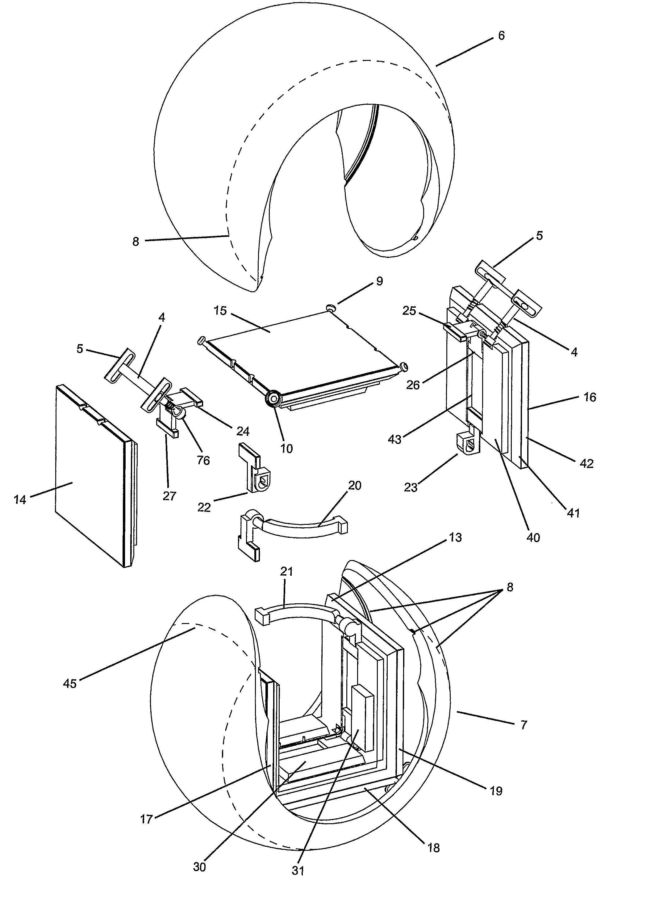
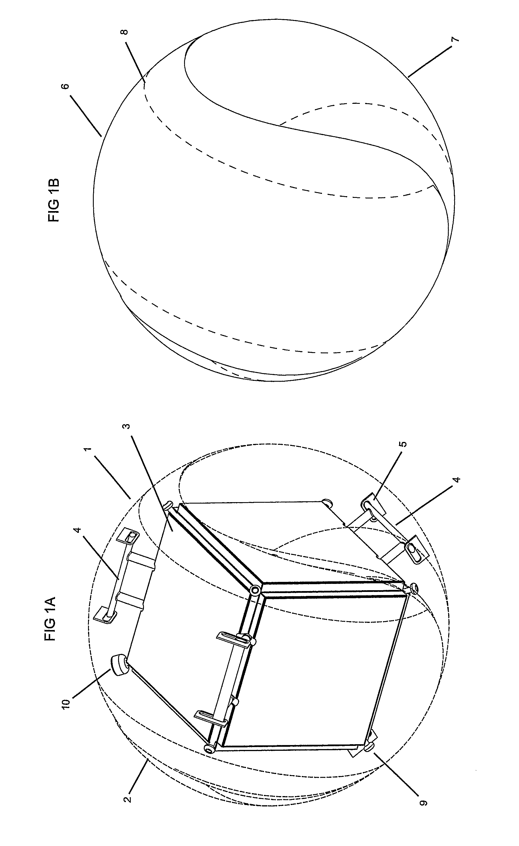
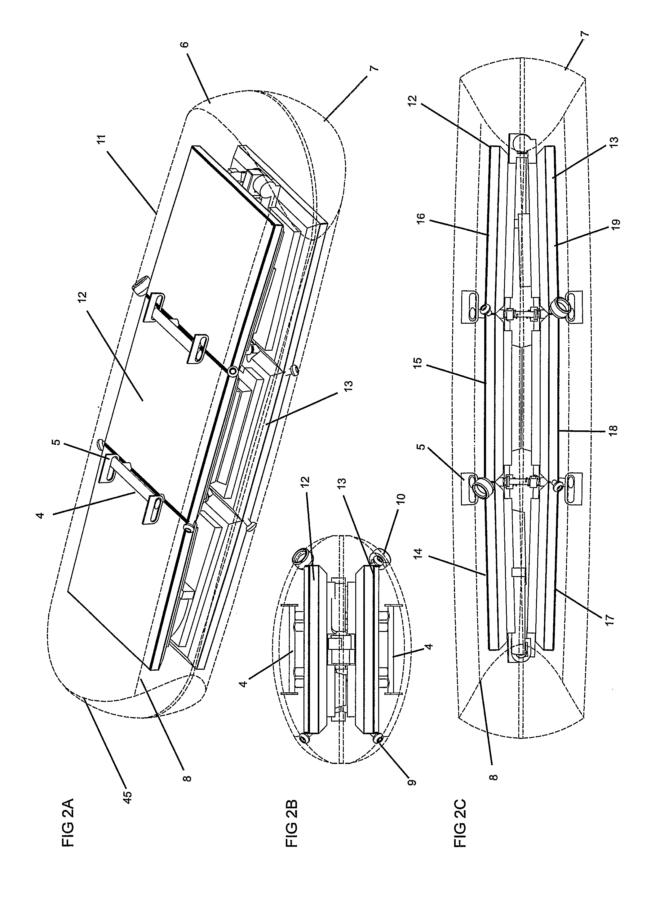
[0049] Referring to FIG. 1A, which shows a 3-dimensional profile of an overall spherical display and control device 1 in its spherical configuration which comprises a flexible transparent sphere shell 2 affixed to a central cube assembly 3 by means of sprung support bar assemblies 4 sliding within grooves 5 attached to the interior surface of the sphere 2. At the corners of the central cube assembly 3 are pegs 9 and an external connector socket 10. FIG. 1B shows the external profile of the overall sphere 2 which is formed from two interlocking identical flexible ‘dog bone’ shaped curved sections 6 and 7 each containing grooved recesses 8 on their underside to facilitate folding. The edges 44 (FIG. 5) of sections 6 and 7 are preferably magnetic either as a magnetic strip attached along said edges or in particle form embedded within the transparent sphere shell edge, such that the two surfaces interlock together as a sphere both mechanically from the biasing action of the elastic flex...


PUM


Abstract

A spherical display and control device, that is preferably collapsible between a spherical configuration and a collapsed generally cylindrical ellipsoid configuration, comprising a flexible transparent spherical surface sprung attached to a central hinged modular cube assembly that contains digital displays on outward faces, and circuitry, battery units and electronic modules on inward surfaces, where said sphere surface contains surface position sensing layers and said central cube contains gyroscopic and inertial sensing devices to provide spherical rotation, and physical displacement data for three dimensional control applications, where said displays preferably have curved polarizer lenses such that the overall device appears as a spherical display or are flat to form an overall Cuboid display or are combined with a flexible spherical display surfaces. The overall device being mechanically biased such that it is Bi-stable between the spherical and collapsed configuration via the action of pulling open and rotating the central cube halves.

Description

BACKGROUND OF THE INVENTION [0001] 1) Field of the Invention [0002] The present invention relates to a spherical display and control device. [0003] This invention in preferred embodiments relates to a collapsible spherical display and control device suitable for 3 D mouse control as a computer input device and used as an interactive display for virtual space navigation, alerts and complex information selection or used as a portable interactive spherical display for data, remote application control, interactive games or ornamental purposes. [0004] 2) Background of the Invention [0005] The increased complexity of computing and data representation is leading to new forms of data visualization where information can be displayed in 3D, virtual or interactive spaces. Similarly web-navigation systems are emerging where sites and landscapes are displayed as a virtual 3D environment or superimposed onto a real world view. Furthermore desk-top environments are also examining 3D vector-graphic...

Claims


Application Information

Patent Timeline
IPC IPC(8): G09G5/00G06F1/16G06F3/0346G06F3/041G06F3/0481G09G3/00
CPCG06F1/1601G06F1/1605G06F1/1607G06F1/1613G06F1/1632G06F2200/1637G06F1/1656G06F1/1694G06F3/0346G06F3/041G06F3/04815G06F1/1641
Inventor DANIEL, SIMON RICHARDWRIGHT, CHRISTOPHER VERITYWELLAND, SIMON BRUCE
Owner DANIEL SIMON
Why Eureka
Try Eureka