
Exercise Machine With Variable Resistance System

Active Publication Date: 2016-03-03
LAGREE TECH INC
View PDF12 Cites 86 Cited by
  • Summary
  • Abstract
  • Description
  • Claims
  • Application Information

AI Technical Summary

Benefits of technology

The patent describes an improved exercise machine that allows for fast and easy selection of different resistance levels using a single inputting means. The machine includes multiple actuation assemblies with different resistance forces, making it simple for the user to choose the desired level of exercise. Additionally, the machine can reversible the direction of the resistance force, allowing for a more versatile workout experience.

Problems solved by technology

Therefore, a bicep machine does not appreciably exercise triceps, and a triceps machine does not appreciably exercise the biceps.
A disadvantage of attempting to perform circuit or interval training on a variety of exercise apparatuses by immediately and without an appreciable rest period, moving from one apparatus for one exercise, to another apparatus for a subsequent exercise is that in a typical gym environment, there will be another exerciser already working out on the next apparatus in the sequence, forcing the circuit exerciser to wait until the apparatus is available.
Another disadvantage of performing circuit training using multiple apparatuses in sequence within a gym environment is that even if the next apparatus is vacant, the proper weight or resistance level must be re-set for each exerciser.
In many instances, this is time consuming, confusing, and the proper weight setting cannot be readily determined.
Again, the break in the circuit sequence reduces the intended advantages of the circuit training session.
A disadvantage of attempting to perform a variation of circuit training upon a single exercise apparatus is that an exerciser must stop the exercise routine, most often by having to dismount the apparatus in order to change the existing resistance settings to new settings.
It often takes more time to change the resistance settings than the period of time the exerciser will actually perform the new exercise at the new setting.
Whether located laterally to the parallel rails, between the parallel rails, or a combination of in between and laterally to the rails, the bias members create obstacles to safely mounting or dismounting the apparatus, and are inherently injury-causing.
It is therefore well known to those skilled in the art that most injuries in Pilates occur during mounting or dismounting, so this process also increases the risk of injury.
Although one advantage of using a Pilates apparatus for a circuit-type of training is that the exerciser will never have to break their workout session by waiting for another exerciser to vacate the apparatus, the major disadvantage is that the exerciser must still stop their workout between exercises to make spring changes.
This is disruptive for the class, the delays thereby causing the class time to run over the allotted time period in order to complete the full allotted exercising time.
Contemporary Pilates apparatuses therefore increase the likelihood of injury, and are exceedingly difficult for an exerciser to determine the proper resistance levels and quickly make corrections without class disruption, all of which are commercially detrimental to the operations of the gym or Pilates studio.
Delays disrupt the classes; cause the exercisers to become frustrated, and ultimately limiting the number of classes that can be conducted during the day resulting in lost revenues for the gym or studio.
As can readily be seen in the immediately preceding example, the necessity of stopping the interval routine to dismount the apparatus to change resistance settings breaks the work cycle, thereby significantly diminishing the intended benefits of the interval training.
Still another disadvantage of all of the exercise machines and Pilates apparatuses just described is that the resistance is unidirectional.
In other words, none of the machines provide for an exerciser to immediately change the direction of the resistance force.
Not only would this be an unnatural exercise, reversing a treadmill belt during exercise would be dangerous, and would likely be the source of many injuries.
On the other hand, there is no provision to allow the exerciser to switch resistance direction so they can push upward on the bar and lift the weights to exercise the shoulders as would be provided by a shoulder press machine.

Method used


Image

  • Exercise Machine With Variable Resistance System
  • Exercise Machine With Variable Resistance System
  • Exercise Machine With Variable Resistance System

Examples


Embodiment Construction

[0062]Various aspects of specific embodiments are disclosed in the following description and related drawings. Alternate embodiments may be devised without departing from the spirit or the scope of the present disclosure. Additionally, well-known elements of exemplary embodiments will not be described in detail or will be omitted so as not to obscure relevant details. Further, to facilitate an understanding of the description, a discussion of several terms used herein follows.

[0063]The word “exemplary” is used herein to mean “serving as an example, instance, or illustration.” Any embodiment described herein as “exemplary” is not necessarily to be construed as preferred or advantageous over other embodiments. Likewise, the term “embodiments” is not exhaustive and does not require that all embodiments include the discussed feature, advantage or mode of operation.

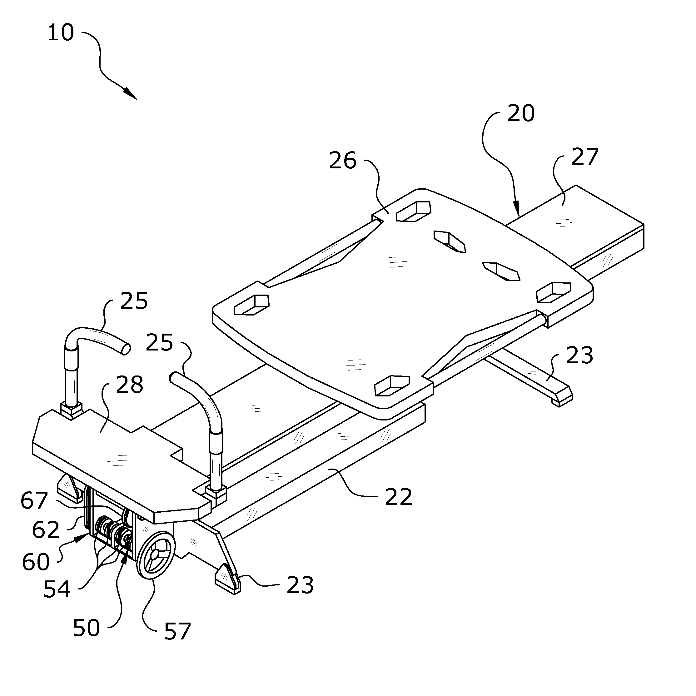
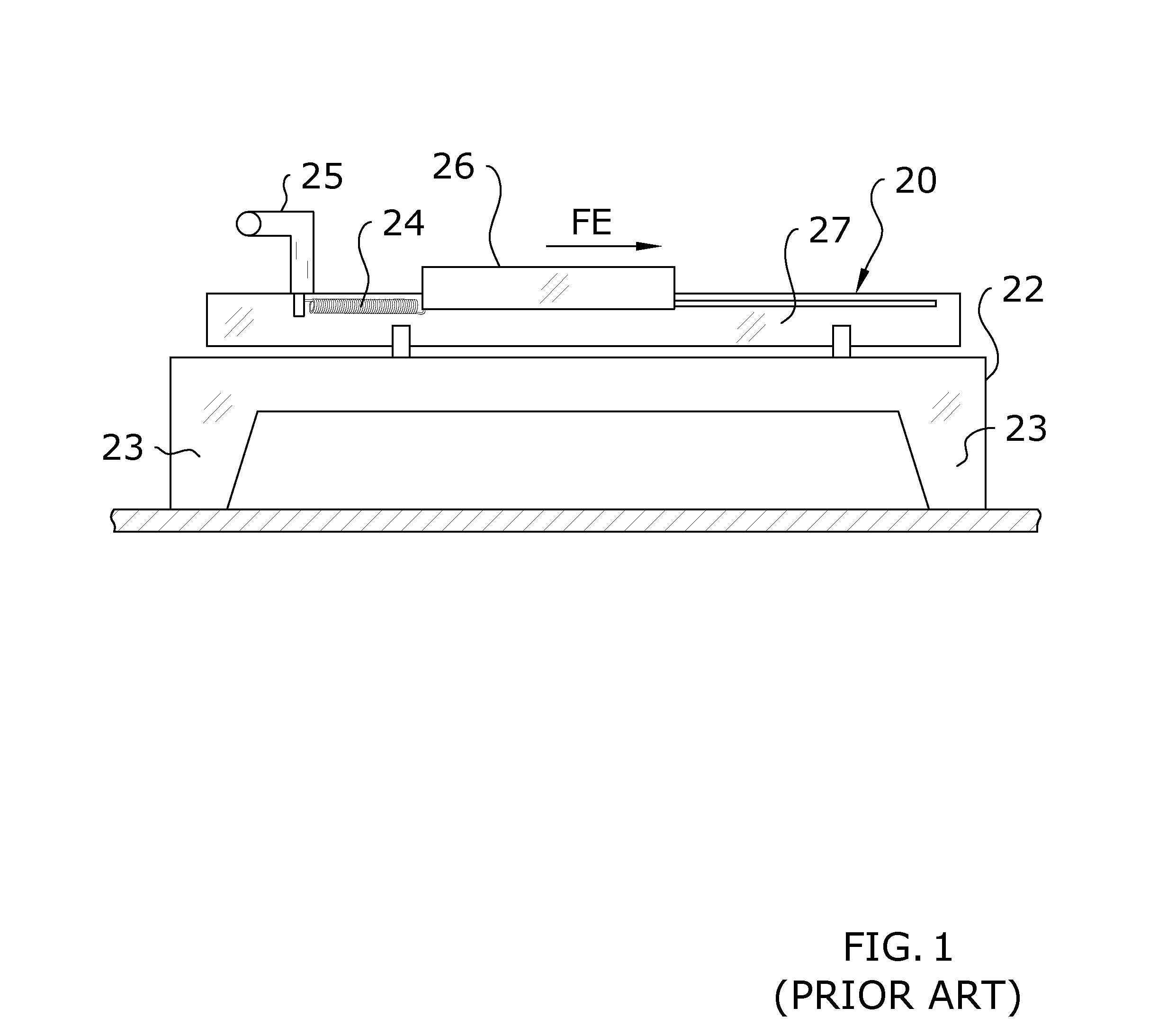
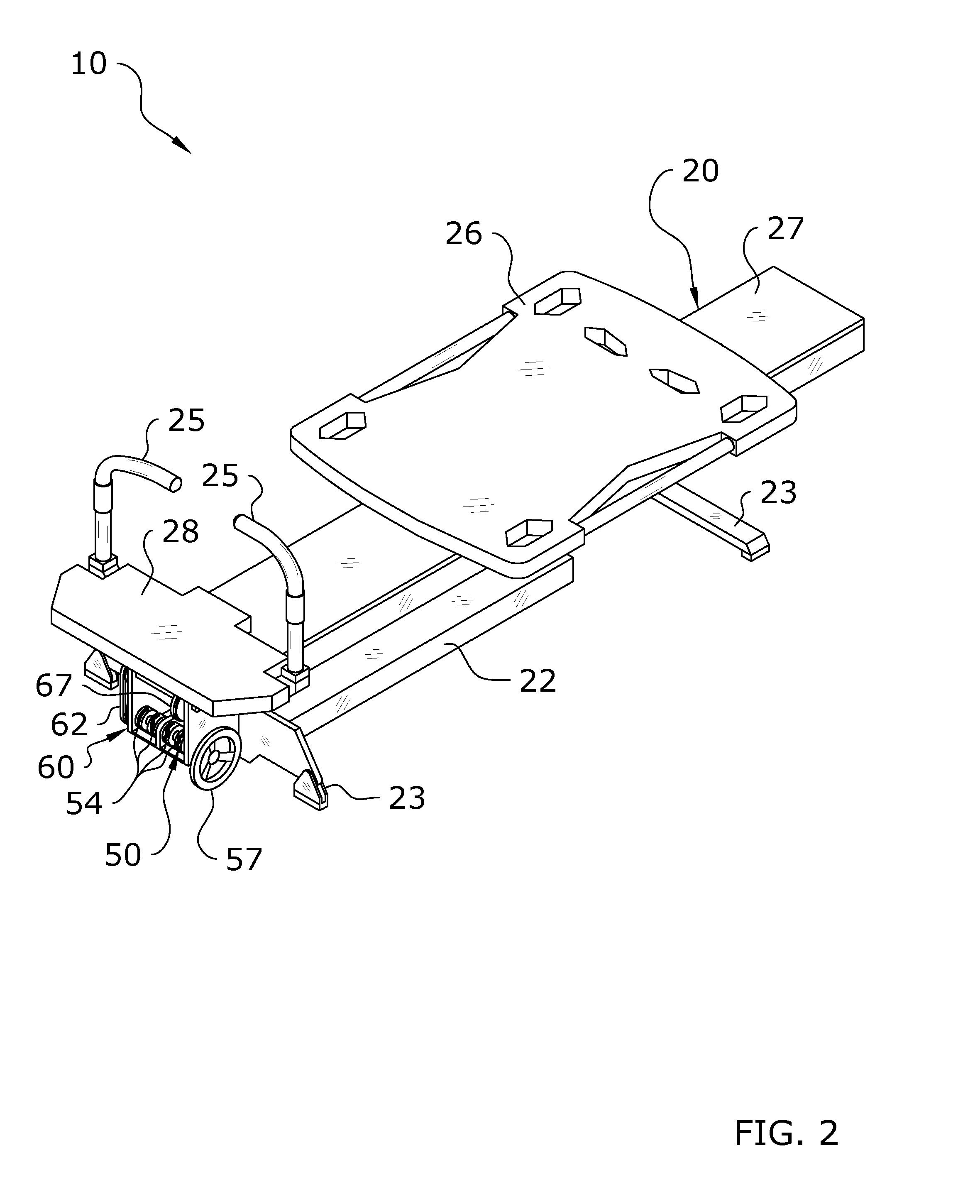
[0064]Provided herein is an exercise machine with variable resistance system 10 which includes a frame 22, a variable resist...


PUM


Abstract

The exercise machine with a variable resistance system includes a frame, an exercise implement movably connected to the frame, a main shaft rotatably connected to the frame, a main connector attached between the main shaft and the exercise implement, a plurality of resistance assemblies and a plurality of actuation assemblies adapted for selectively engaging or disengaging at least one of the plurality of resistance assemblies with respect to the main shaft. The plurality of resistance assemblies apply a total level of rotational resistance against the main shaft based on which of the plurality of resistance assemblies are engaged with the main shaft by the plurality of actuation assemblies.

Description

CROSS REFERENCE TO RELATED APPLICATIONS[0001]I hereby claim benefit under Title 35, United States Code, Section 119(e) of U.S. provisional patent application Ser. No. 62 / 043,503 filed Aug. 29, 2014. The 62 / 043,503 application is currently pending. The 62 / 043,503 application is hereby incorporated by reference into this application.STATEMENT REGARDING FEDERALLY SPONSORED RESEARCH OR DEVELOPMENT[0002]Not applicable to this application.BACKGROUND OF THE INVENTION[0003]1. Field of the Invention[0004]The present invention relates generally to an improved exercise machine and more specifically it relates to an exercise machine with variable resistance system for selecting one of many different resistance forces being applied to an exercise implement.[0005]2. Description of the Related Art[0006]Any discussion of the related art throughout the specification should in no way be considered as an admission that such related art is widely known or forms part of common general knowledge in the f...

Claims


Application Information

Patent Timeline
IPC IPC(8): A63B21/00A63B23/12A63B24/00
CPCA63B21/00065A63B21/157A63B24/0087A63B23/12A63B21/154A63B21/023A63B21/0428A63B21/0557A63B22/203A63B22/205A63B23/03516A63B23/1263A63B21/0059A63B21/4031A63B21/4035A63B22/0087
Inventor LAGREE, SEBASTIEN, ANTHONY, LOUISO'BRIEN, MATTHEWBALZER, WILLIAM
Owner LAGREE TECH INC
Learn More