Techniques for beam shaping at a millimeter wave base station and a wireless device and fast antenna subarray selection at a wireless device

a technology of millimeter wave base station and wireless device, which is applied in the field of wireless communication, can solve the problems of high path loss, frequent high path loss, and increased resource consumption of millimeter wave communications, and achieve the effect of improving link margins and improving user equipment discovery latency

Active Publication Date: 2016-07-07
QUALCOMM INC
View PDF7 Cites 88 Cited by
  • Summary
  • Abstract
  • Description
  • Claims
  • Application Information

AI Technical Summary

Benefits of technology

[0009]Systems, methods, and apparatuses for beam shaping at a millimeter wave base station, and for fast selection of an antenna subarray at a wireless device are described. In accordance with the present disclosure, a wireless communications system may improve user equipment (UE) discovery latency by dynamically selecting and switching beamforming codebooks at the millimeter wave base station and the wireless device. Selecting an optimal beamforming codebook may allow the wireless communication system to improve link margins between the base station without compromising resources. In some examples, a wireless device may determine whether the received signals from the millimeter wave base station satisfy established signal to noise (SNR) thresholds. The wireless device may then select an optimal beam codebook to establish communications with the millimeter wave base station. Additionally or alternately, the wireless device may further signal the selected beam codebook to the millimeter wave base station and direct the millimeter wave base station to adjust its codebook based on the selection.

Problems solved by technology

Millimeter wavelength signals, however, frequently experience high path loss, and as a result, directional beam forming techniques may be used for uplink (UL) and / or downlink (DL) transmissions between a base station and a UE using millimeter wavelength frequencies.
The reliance on directional beams, however, may make millimeter wave communications more resource-intensive.
However, in some cases, a position of the hand holding the mobile device and / or near-field effects due to the body may interfere with signals received at a plurality of antennas at the UE.

Method used


Image

  • Techniques for beam shaping at a millimeter wave base station and a wireless device and fast antenna subarray selection at a wireless device
  • Techniques for beam shaping at a millimeter wave base station and a wireless device and fast antenna subarray selection at a wireless device
  • Techniques for beam shaping at a millimeter wave base station and a wireless device and fast antenna subarray selection at a wireless device

Examples


Embodiment Construction

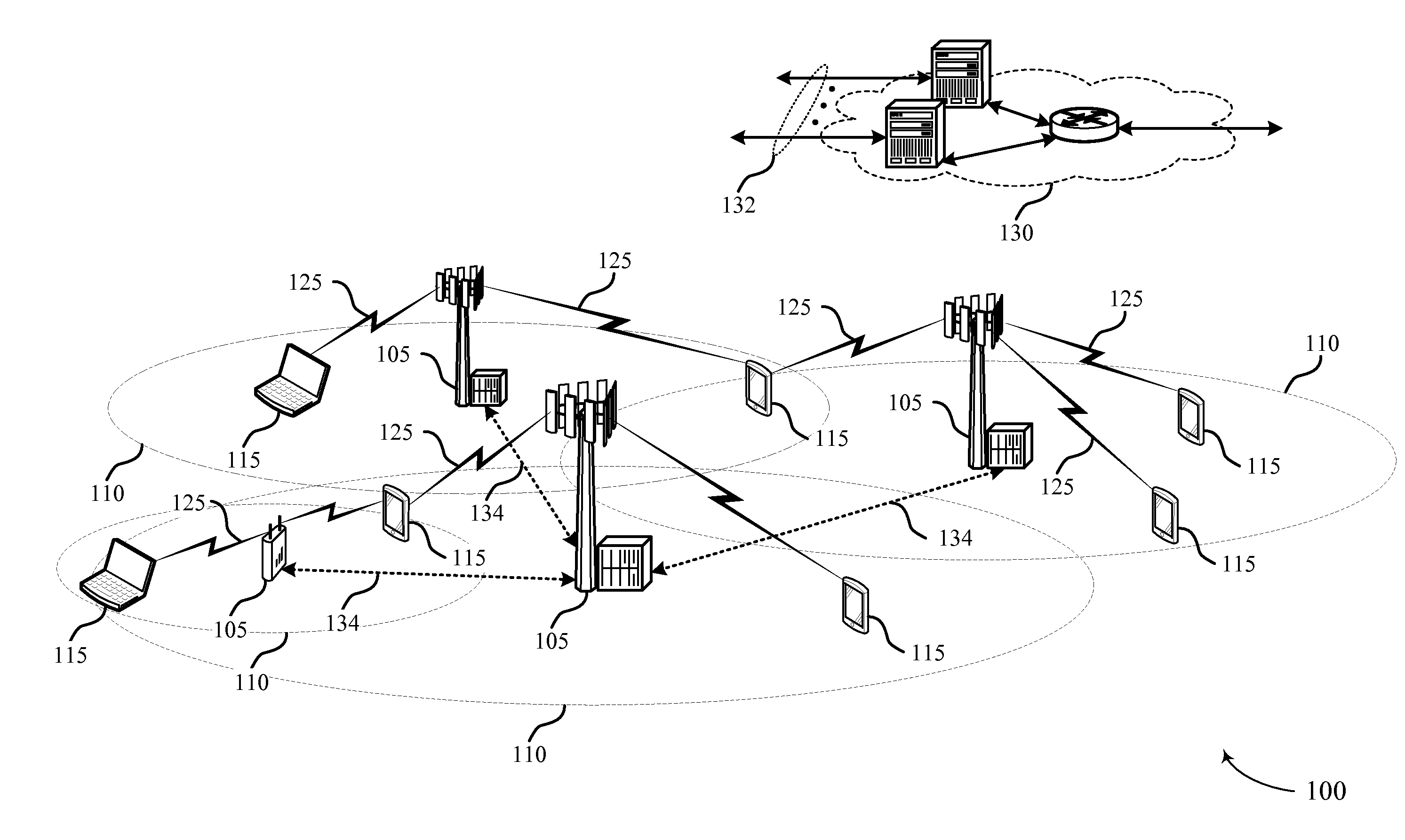
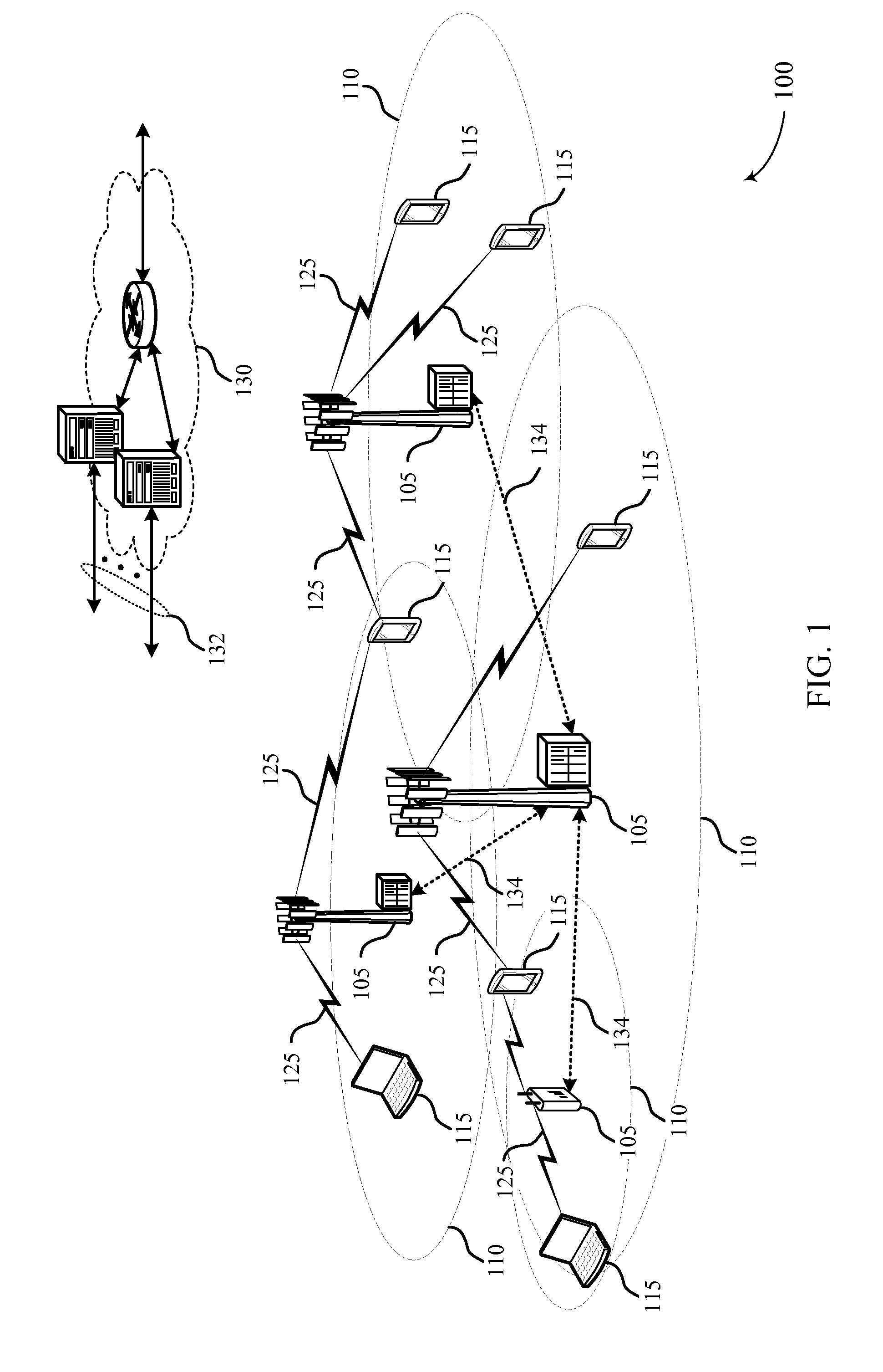
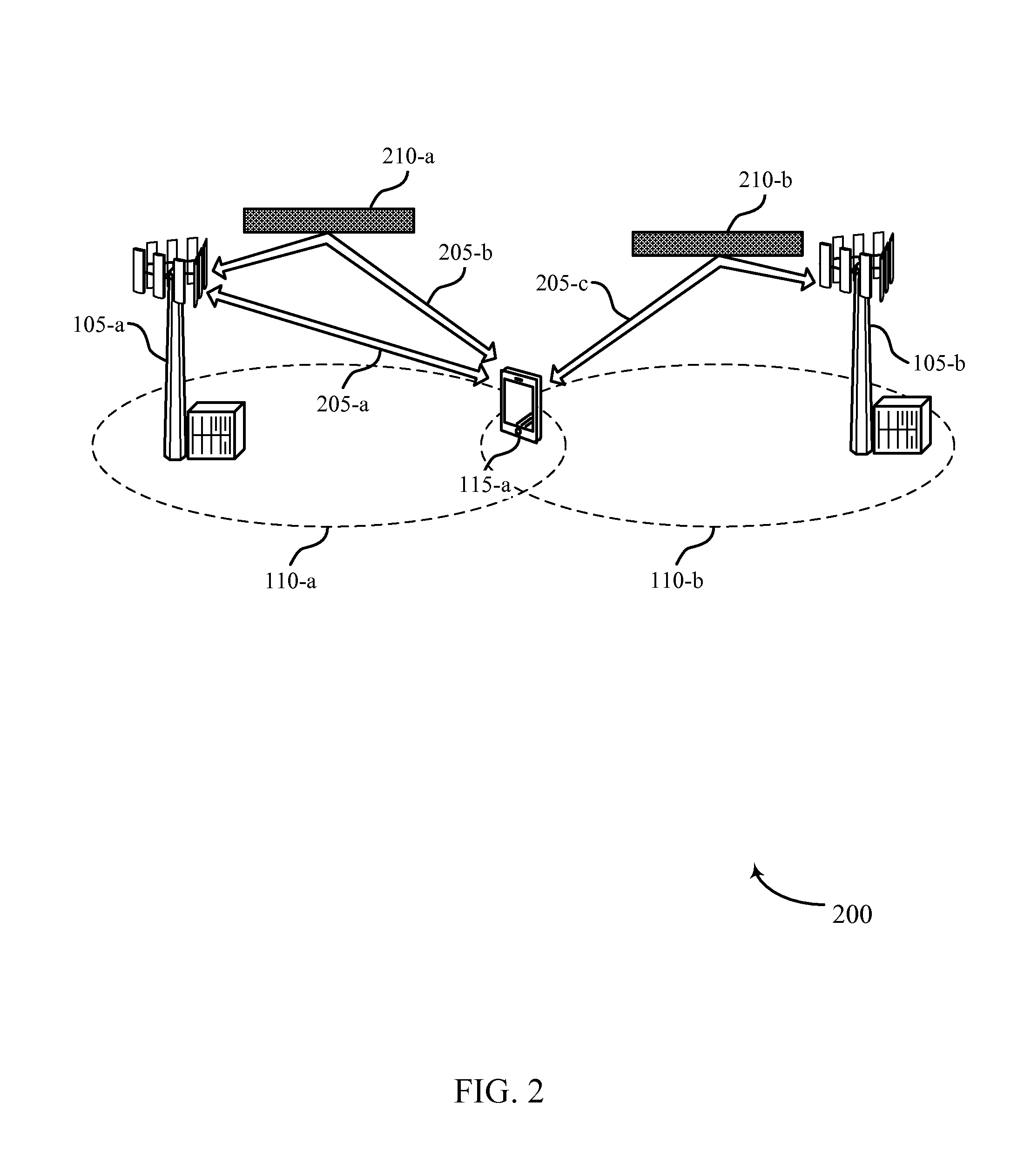
[0057]The described features generally relate to improved systems, methods, or apparatuses for beam shaping at a millimeter wave base station and a wireless device. As discussed above, millimeter wavelength signals frequently experience high path loss, and as a result, directional beam forming techniques may be used for uplink (UL) or downlink (DL) transmissions between a base station and a UE using millimeter wavelength frequencies. Directional beamforming techniques may enable a transmitter to transmit a signal onto a particular propagation path, and may enable a receiver to receive a signal from a particular propagation path.

[0058]The quality of link margins between the base station and the UE, however, may be dependent on a number of factors, including the location of the UE in relation to the millimeter wave base station or the type of codebook utilized by the base station and the UE for beamforming. For example, while broader beam codebooks (e.g., coarse codebook or intermedia...


PUM


Abstract

Methods, systems, and devices are described for wireless communication at a user equipment (UE). A wireless communications system may improve UE discovery latency by dynamically selecting and switching beam forming codebooks at the millimeter wave base station and the wireless device. Selecting an optimal beam forming codebook may allow the wireless communication system to improve link margins between the base station without compromising resources. In some examples, a wireless device may determine whether the received signals from the millimeter wave base station satisfy established signal to noise (SNR) thresholds, and select an optimal beam codebook to establish communication. Additionally or alternately, the wireless device may further signal the selected beam codebook to the millimeter wave base station and direct the millimeter wave base station to adjust its codebook based on the selection.

Description

CROSS REFERENCES[0001]The present application for patent claims priority to U.S. Provisional Patent Application No. 62 / 100,350 by Raghavan et al., entitled “Techniques for Beam Shaping at a Millimeter Wave Base Station and a Wireless Device,” filed Jan. 6, 2015, and U.S. Provisional Patent Application No. 62 / 100,352 by Raghavan et al., entitled “Techniques for Fast Selection of an Antenna Subarray and Beamforming for Millimeter Wave Wireless Connections,” filed Jan. 6, 2015, both assigned to the assignee hereof, and expressly incorporated by reference herein.BACKGROUND[0002]1. Field of Disclosure[0003]The following relates generally to wireless communications, and more specifically to techniques for beam shaping at a millimeter wave base station and for fast selection of an antenna subarray at a wireless device.[0004]2. Description of Related Art[0005]Wireless communications systems are widely deployed to provide various types of communication content such as voice, video, packet da...

Claims


Application Information

Patent Timeline
Patent Type & Authority Applications(United States)
IPC IPC(8): H04W72/04H04W72/08H04B7/06
CPCH04W72/0466H04W72/085H04B7/0617H04B7/0456H04B7/0639H04B7/0874H04W72/542
Inventor RAGHAVAN, VASANTHANCEZANNE, JUERGENSUBRAMANIAN, SUNDARSAMPATH, ASHWINLI, JUNYI
Owner QUALCOMM INC
Why Eureka
Try Eureka