
Systems and methods for additional retransmissions of dropped packets

a technology of dropped packets and retransmission methods, applied in data switching networks, frequency-division multiplexes, instruments, etc., can solve the problems of slow application response times, inability to guarantee latency of bandwidth allocation, and difficulty in identifying interactive traffic, so as to improve network latency and avoid additional delays

Active Publication Date: 2007-09-06
CITRIX SYST INC
View PDF102 Cites 85 Cited by
  • Summary
  • Abstract
  • Description
  • Claims
  • Application Information

AI Technical Summary

Benefits of technology

[0007] The present invention is directed towards systems and methods for utilizing transaction boundary detection methods in queuing and retransmission decisions relating to network traffic. By detecting transaction boundaries and sizes, a client, server, or intermediary device may prioritize based on transaction sizes in queuing decisions, giving precedence to smaller transactions which may represent interactive and / or latency-sensitive traffic. Further, after detecting a transaction boundary, a device may retransmit one or more additional packets prompting acknowledgements, in order to ensure timely notification if the last packet of the transaction has been dropped. The present invention is also directed to other retransmission systems and methods for potentially improving network latency, including retransmitting a dropped packet twice or more in order to avoid incurring additional delays due to a retransmitted packet being lost.
[0010] In a third aspect, the present invention relates to methods for reducing transmission timeouts by selectively transmitting additional packets from an intermediary device based on identifying transaction boundaries. In one embodiment, the method comprises: receiving, by a device via a transport layer connection between a sender and a receiver, a first packet from the sender via the first transport layer connection; transmitting, by the device, the first packet to the receiver; determining, by the device, that the first packet is smaller than a maximum packet size of the transport layer connection; generating, by the device in response to the determination, at least one additional packet; and transmitting, by the device after the first packet has been transmitted to the receiver, the at least one additional packet to the receiver via the transport layer connection.
[0012] In a fifth aspect, the present invention relates to methods for retransmitting network packets between a sender and a receiver to reduce transmission errors associated with a transport layer connection. In one embodiment, a method comprises: receiving, by a device, an indication that a network packet transmitted via a transport layer connection was not received by the receiver; retransmitting, by the device, the network packet to the receiver in response to the indication; determining, by the device, a packet loss rate associated with the transport layer connection; determining, by the device in response to the determined packet loss rate, a number of additional retransmissions; and retransmitting, by the device, the network packet in accordance with the determined number of additional retransmissions.
[0013] In a sixth aspect, the present invention relates to systems for retransmitting network packets between a sender and a receiver to reduce transmission errors associated with a transport layer connection. In one embodiment, a system comprises: a packet processor which receives an indication that a network packet transmitted via a transport layer connection was not received by the receiver; and retransmits the network packet to the receiver in response to the indication; and a flow controller in communication with the packet processor which determines a packet loss rate associated with the transport layer connection; determines, in response to the determined packet loss rate, a number of additional retransmissions; and retransmits the network packet in accordance with the determined number of additional retransmissions.

Problems solved by technology

By contrast, interactive traffic, such as VoIP, remote procedure calls, media streaming, application streaming, and remote application execution, may be dramatically affected by changes in latency which lead to slower application response times.
Existing quality of service (QoS) systems may attempt to prioritize interactive traffic to reduce latency, but may face several difficulties.
First, bandwidth-allocation methods of QoS may ensure that a certain amount of interactive traffic has the bandwidth to pass through a network, but the bandwidth allocation may have no guarantee of latency.
Second, interactive traffic may be difficult to identify.
Thus, simply prioritizing packets based on a port or underlying application may not properly identify latency sensitive traffic.
An additional potential cause of latency with respect to interactive or streaming traffic is dropped packets.
Dropped packets can impose additional costs on traffic containing, such as interactive or streaming traffic, which may contain significant gaps between transmitted packets.
Where these gaps occur, a receiver may not be able to identify if a packet immediately preceding the gap was lost since there are no subsequent packets to inform the receiver that the last packet existed.
However, RTOs may provide only coarse control over delays induced by packet losses.
In some protocols, RTOs can be very expensive, such as TCP, where the RTO is by default a full second.
In addition to standard retransmission delays, extra delays may be incurred when a retransmitted packet is also dropped.
In some cases, the dropping of a retransmitted packet may cause a delay equal to a full round trip time.
This delay may have severe effects on time-sensitive network traffic.

Method used


Image

  • Systems and methods for additional retransmissions of dropped packets
  • Systems and methods for additional retransmissions of dropped packets
  • Systems and methods for additional retransmissions of dropped packets

Examples


Embodiment Construction

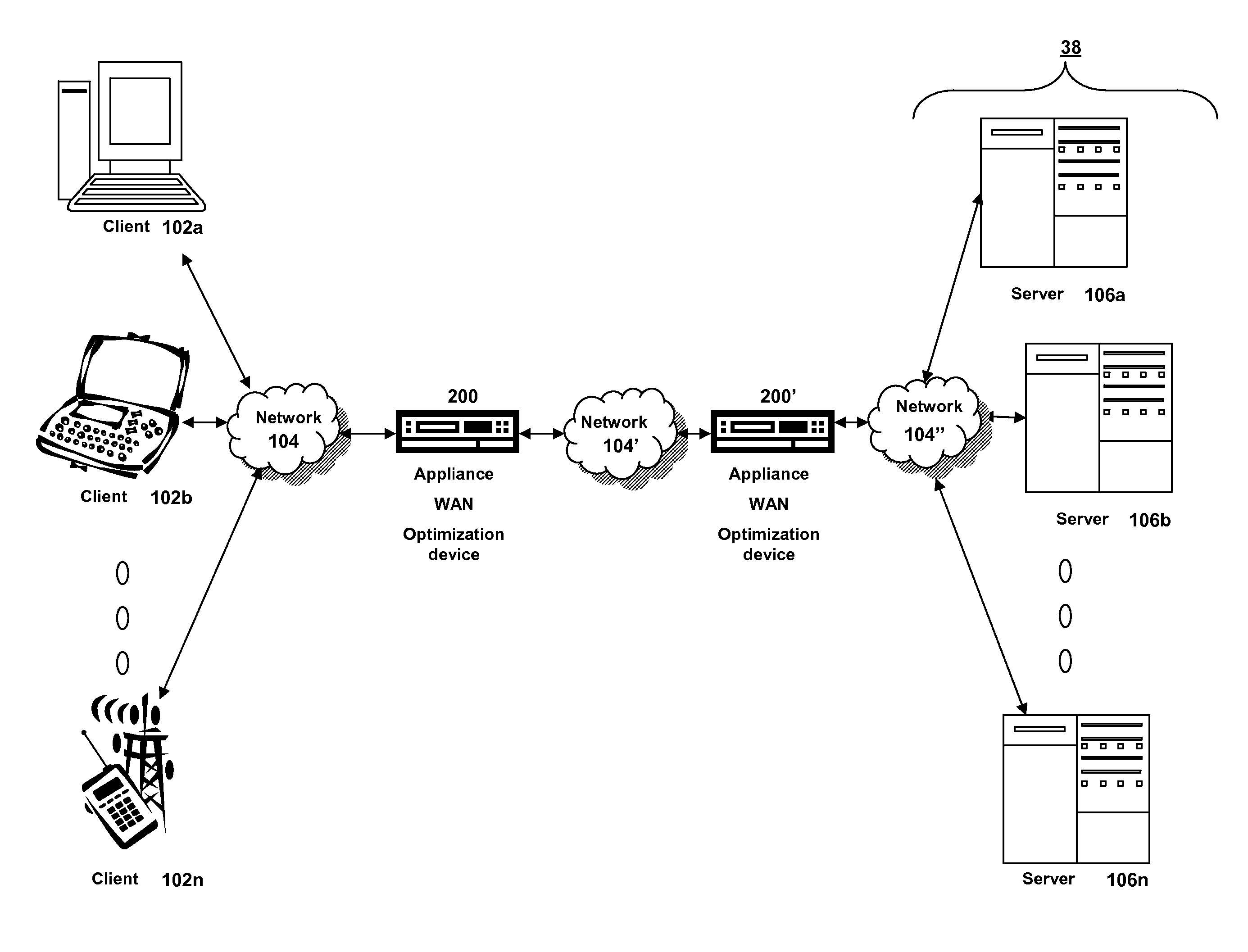
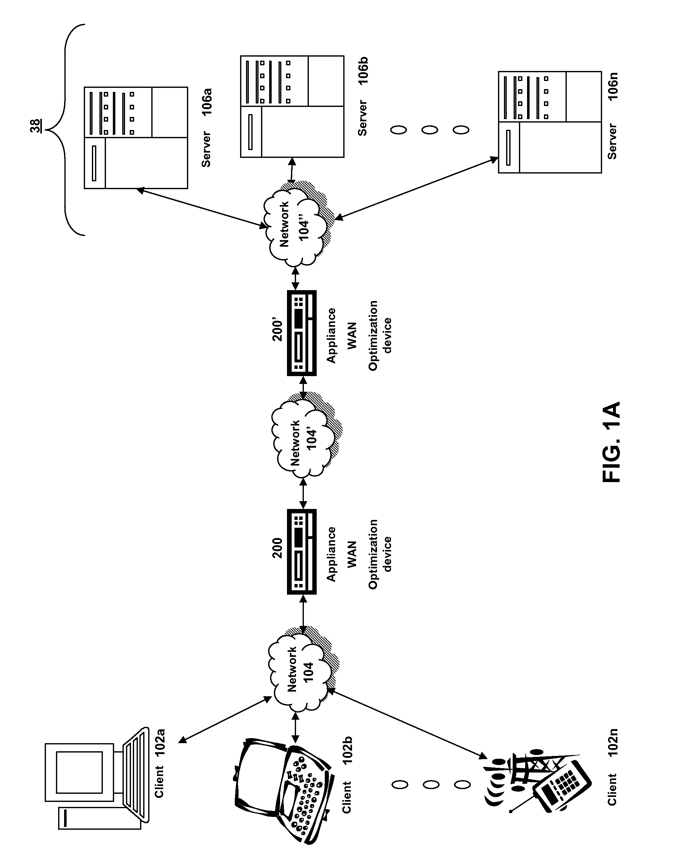
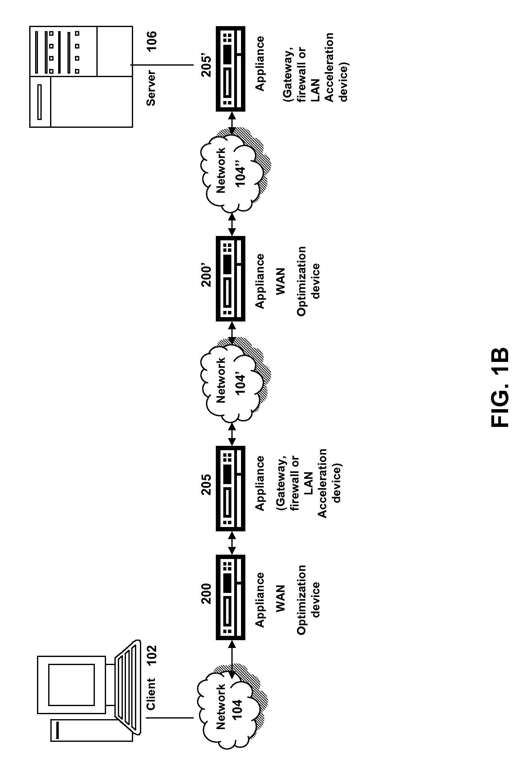
[0030] For purposes of reading the description of the various embodiments of the present invention below, the following descriptions of the sections of the specification and their respective contents may be helpful: [0031] Section A describes a network environment and computing environment useful for practicing an embodiment of the present invention; [0032] Section B describes embodiments of a system and appliance architecture for accelerating delivery of a computing environment to a remote user; [0033] Section C describes embodiments of a client agent for accelerating communications between a client and a server; [0034] Section D describes embodiments of systems and methods for using transaction boundaries to determine transmission priorities; and [0035] Section E describes embodiments of systems and methods for reducing timeout penalties and costs associated with network connections

A. Network and Computing Environment

[0036] Prior to discussing the specifics of embodiments of th...


PUM


Abstract

Systems and methods for utilizing transaction boundary detection methods in queuing and retransmission decisions relating to network traffic are described. By detecting transaction boundaries and sizes, a client, server, or intermediary device may prioritize based on transaction sizes in queuing decisions, giving precedence to smaller transactions which may represent interactive and / or latency-sensitive traffic. Further, after detecting a transaction boundary, a device may retransmit one or more additional packets prompting acknowledgements, in order to ensure timely notification if the last packet of the transaction has been dropped. Systems and methods for potentially improving network latency, including retransmitting a dropped packet twice or more in order to avoid incurring additional delays due to a retransmitted packet being lost are also described.

Description

RELATED APPLICATIONS [0001] The present application is a continuation-in-part of U.S. patent application Ser. No. 10 / 901,940 filed on Jul. 28, 2004, which is itself a continuation-in-part of U.S. patent application Ser. No. 10 / 696,507 filed on Oct. 29, 2003, which is a nonprovisional application corresponding to the U.S. Provisional Application 60 / 490,694 filed on Jul. 29, 2003.FIELD OF THE INVENTION [0002] The present invention generally relates to data communication networks. In particular, the present invention relates to systems and methods for dynamically controlling bandwidth by a proxy of one or more connections. BACKGROUND OF THE INVENTION [0003] Different types of network traffic have different sensitivity to network performance. With regard to latency, large file transfers may be relatively unaffected by moderate increases in the latency of a connection. By contrast, interactive traffic, such as VoIP, remote procedure calls, media streaming, application streaming, and remo...

Claims


Application Information

Patent Timeline
IPC IPC(8): H04L1/00H04L12/28H04L12/56H04L47/2466
CPCH04L1/1887H04L1/189H04L12/24H04L41/00H04L41/12H04L47/2466H04L69/16H04L69/166H04L67/28H04L67/2876H04L2001/0092H04L67/56
Inventor PLAMONDON, ROBERTOVSIANNIKOV, MICHAELSAMUELS, ALLEN
Owner CITRIX SYST INC
Learn More