Permanent magnet rotating electric machine and electric car using the same

Active Publication Date: 2005-09-15
HITACHI ASTEMO LTD
View PDF5 Cites 131 Cited by
  • Summary
  • Abstract
  • Description
  • Claims
  • Application Information

AI Technical Summary

Benefits of technology

[0019] According to the present invention, an electric car in which the effect of iron loss can be reduced more, and a highly efficient permanent magnet rotating electric machine can be obtained, and fuel expenses can be reduced, and low vi

Problems solved by technology

Hei09(1997)-261901, particularly in a case of a drive motor used in a hybrid electric vehicle, the iron loss due to the magnetic flux of the pe

Method used


Image

  • Permanent magnet rotating electric machine and electric car using the same
  • Permanent magnet rotating electric machine and electric car using the same
  • Permanent magnet rotating electric machine and electric car using the same

Examples


first embodiment

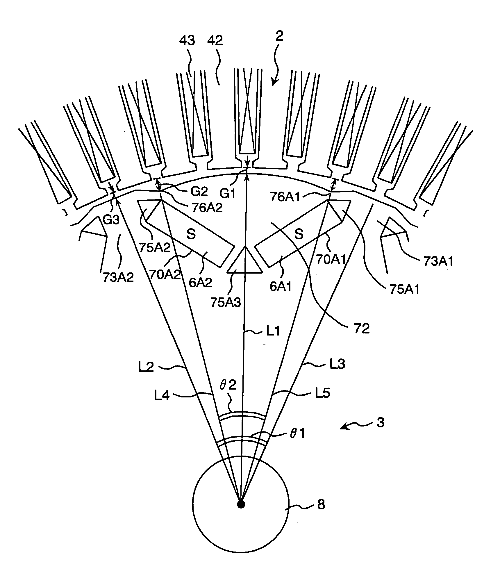
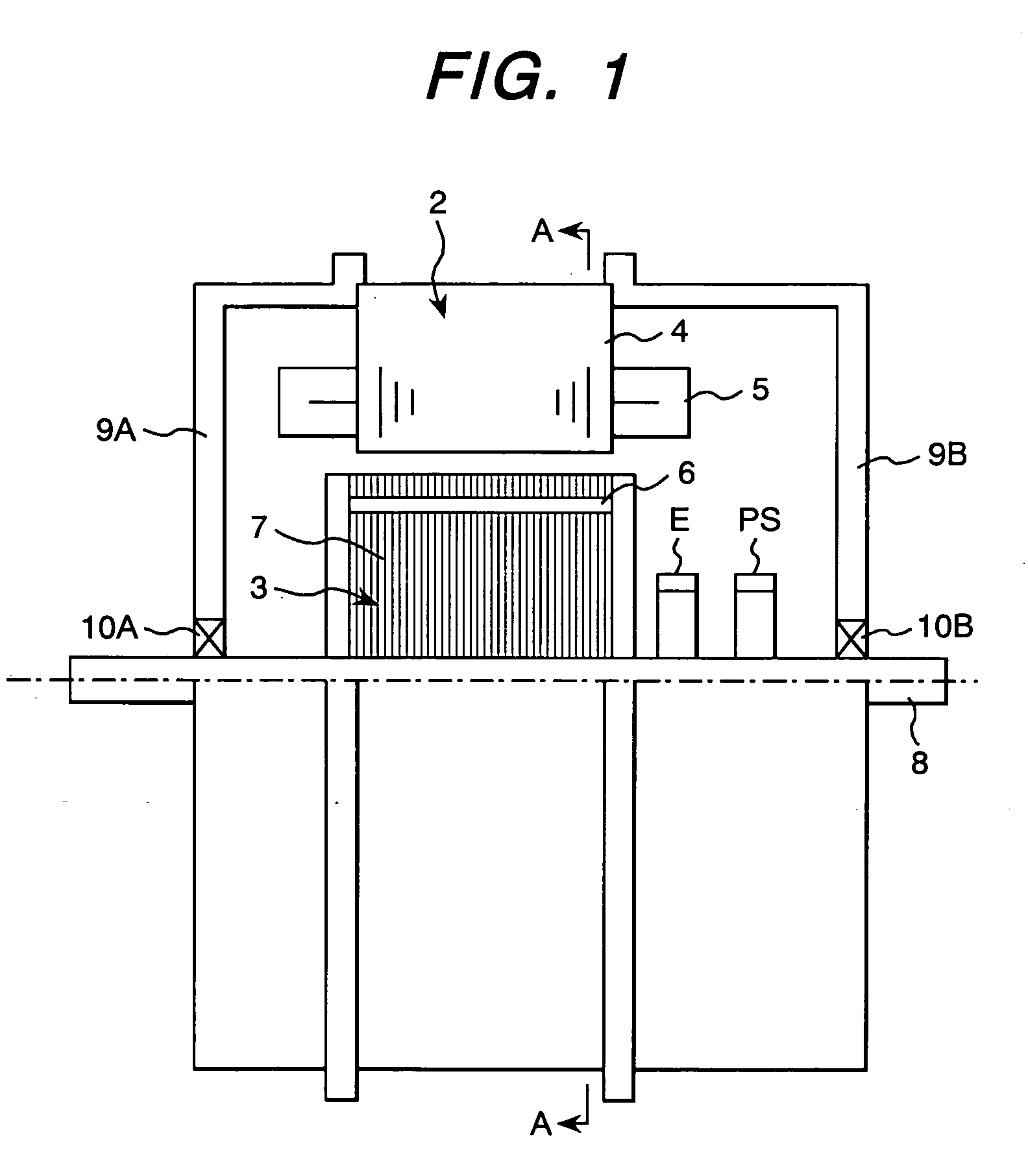
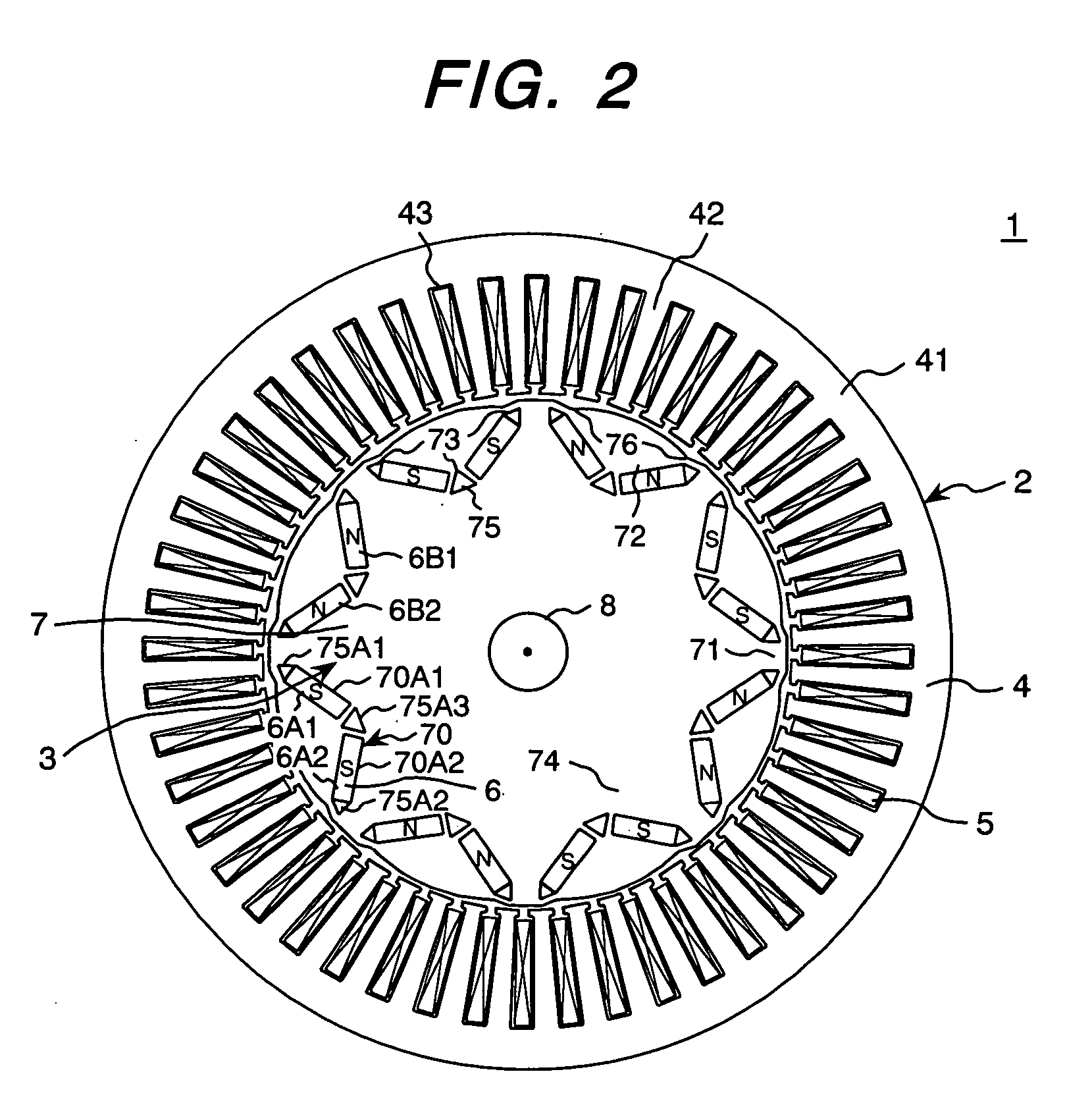
[0034]FIGS. 1 and 2 are cross sectional views showing the constitution of the permanent magnet rotating electric machine of the present invention. FIG. 1 is a cross sectional view in the parallel direction with the rotation axis and FIG. 2 is a cross sectional view in the perpendicular direction to the rotation axis and a view in the A-A direction shown in FIG. 1. Further, in FIGS. 1 and 2, the same numerals indicate the same parts.

[0035] As shown in FIG. 1, a permanent magnet rotating electric machine 1 includes a stator 2, a rotor 3, and end brackets 9A and 9B. The stator 2 has a stator iron core 4 and stator windings 5. The rotor 3 has a rotor iron core 7 composed of a magnetic substance and a shaft 8. Further, the rotor 3, via the shaft 8 fit into the rotor iron core 7, is rotatably held by bearings 10A and 10B fit into the end brackets 9A and 9B. Further, the constitution shown in the drawing has no frame on the outer periphery of the stator iron core 4. However, a frame may be...

second embodiment

[0064] Next, by referring to FIG. 7, the constitution of the permanent magnet rotating electric machine of the present invention will be explained. Here, the whole constitution of the permanent magnet rotating electric machine of this embodiment is the same as that shown in FIG. 1.

[0065]FIG. 7 is a cross sectional view showing the constitution of the permanent magnet rotating electric machine of the second embodiment of the present invention. FIG. 7, similarly to FIG. 2, is a cross sectional view in the direction perpendicular to the rotation axis and a view in the direction of A-A. Further, the same numerals as those shown in FIGS. 1 and 2 indicate the same parts.

[0066] In the constitution shown in FIG. 2, 2 permanent magnets constitute one magnetic pole of the rotor and are arranged in a V shape, while in this embodiment, as shown in FIG. 7, one permanent magnet 6J constitutes one magnetic pole of the rotor and is inserted into an insertion hole 70J in which the long sides of the...

third embodiment

[0071] Next, by referring to FIGS. 8 to 10, the constitution of the permanent magnet rotating electric machine of the present invention will be explained. Here, the whole constitution of the permanent magnet rotating electric machine of this embodiment is the same as that shown in FIG. 1.

[0072]FIG. 8 is a cross sectional view showing the constitution of the permanent magnet rotating electric machine of the third embodiment of the present invention. FIG. 8, similarly to FIG. 2, is a cross sectional view in the direction perpendicular to the rotation axis and a view in the direction of A-A. Further, the same numerals as those shown in FIGS. 1 and 2 indicate the same parts.

[0073] In this embodiment, on the outer peripheral part of the magnetic pole pieces 72 of the rotor 3 of the permanent magnet rotating electric machine 1, at the position of θ4 from the center of the magnetic poles, concavities 77 are installed. The other constitution is the same as that shown in FIG. 2. However, th...


PUM


Abstract

A permanent magnet rotating electric machine comprises a stator having stator windings wound round a stator iron core and a permanent magnet rotor having a plurality of inserted permanent magnets in which the polarity is alternately arranged in the peripheral direction in the rotor iron core. The rotor iron core of the permanent magnets is composed of magnetic pole pieces, auxiliary magnetic poles, and a stator yoke, and furthermore has concavities formed on the air gap face of the magnetic pole pieces of the rotor iron core of the permanent magnets, gently tilting from the central part of the magnetic poles to the end thereof. In a permanent magnet rotating electric machine, effects of iron loss are reduced, and an electric car using highly efficient permanent magnet rotating electric machine are realized.

Description

CLAIM OF PRIORITY [0001] The present application claims priority from Japanese application serial no. 2004-66465, filed on Mar. 10, 2004, the content of which is hereby incorporated by reference into this application. FIELD OF THE INVENTION [0002] The present invention relates to a permanent magnet rotating electric machine suitable for use for an electric car and the electric car using it. BACKGROUND OF THE INVENTION [0003] A motor used to drive an electric car, particularly an electric vehicle and a hybrid electric vehicle, is desired to be small, light, and highly efficient. In recent years, by development of a highly efficient magnet material, as a drive motor for an electric car (particularly an electric vehicle and a hybrid electric vehicle), in consideration of the respect that it can be made smaller, lighter, and more highly efficient than an induction motor and a reluctance motor, a permanent magnet motor has been used predominantly. The reason is that the permanent magnet ...

Claims


Application Information

Patent Timeline
IPC IPC(8): H02K1/24H02K1/27H02K1/22H02K21/12H02K21/14
CPCH02K1/2766Y02T10/642H02K2201/03H02K2213/03Y02T10/641B60L7/14B60L11/1803B60L11/1877B60L15/2009B60L2240/12B60L2240/421B60L2240/423B60L2270/145Y02T10/7005Y02T10/705Y02T10/7275H02K29/03Y02T10/72B60L50/51B60L50/66Y02T10/64Y02T10/70
Inventor TAJIMA, FUMIOMATSUNOBU, YUTAKAKITAMURA, MASASHIHINO, NORIAKIKOBAYASHI, TAKASHIKAKUGAWA, SHIGERUYASUHARA, TAKASHI
Owner HITACHI ASTEMO LTD
Why Eureka
Try Eureka