Device and method for mounting a turbine engine

a turbine engine and device technology, applied in the direction of machines/engines, machine supports, liquid fuel engines, etc., can solve the problems of disruptive structural resonances of this kind, almost unavoidable vibrations in operation, and theoretically precise predictive calculations of disruptive structural resonances. , to achieve the effect of reducing vibration

Inactive Publication Date: 2009-03-12
ANSALDO ENERGIA IP UK LTD
View PDF9 Cites 137 Cited by
  • Summary
  • Abstract
  • Description
  • Claims
  • Application Information

AI Technical Summary

Benefits of technology

[0007]A method for mounting a turbine engine is disclosed, e.g., a gas turbine system, such that vibration is reduced, in which a rotor unit is mounted to rotate inside a stationary external housing, having at least two supports for taking up the weight of the turbine engine, these supports being arranged at a spacing from one another in an axial longitudinal direction in relation to the external housing and at one side being articulated directly or indirectly on the external housing and at the other side being supported directly or indirectly on a base frame, wherein there is provided on at least one support a horizontally oriented support face, which is arranged vertically opposite a bearing face that is provided on the base frame, and wherein between the support face and the bearing face there are inserted at least two laterally spaced from each other support plate elements such that the force of the weight of the turbine engine bears on the base frame entirely by way of the support plate elements, such that in operation of the turbine engine vibration is minimized.

Problems solved by technology

It is clear that vibrations in operation as a result of the large masses set in rotation by the rotor unit 6 are almost unavoidable and will become clearly evident in the form of structural resonance, in particular close to the rated operational speed of rotation of the gas turbine system, and depending on their intensity will at the least impair start-up of the gas turbine system and at worst will make it impossible.
Making a theoretically precise predictive calculation of disruptive structural resonance of this kind is on the one hand very complex and yet on the other cannot be performed with a satisfactory degree of precision, the more so since once a gas turbine system has been installed broad variations in the frequency at which the respective structural resonance appears will occur.
Thus, it is perfectly possible for disruptive structural resonance to occur below or above the respective operational speeds of rotation, in some cases even with gas turbine systems of the same construction.
Not least for economic reasons, it is essential to keep the vibration which occurs in operation with gas turbine systems within acceptable limits, the more so since excessive vibration will put the operational reliability of the entire gas turbine system in doubt and ultimately result in a costly decommissioning of the entire gas turbine system.

Method used


Image

  • Device and method for mounting a turbine engine
  • Device and method for mounting a turbine engine
  • Device and method for mounting a turbine engine

Examples


Embodiment Construction

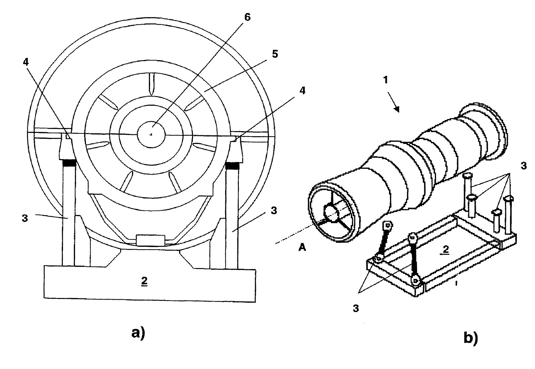
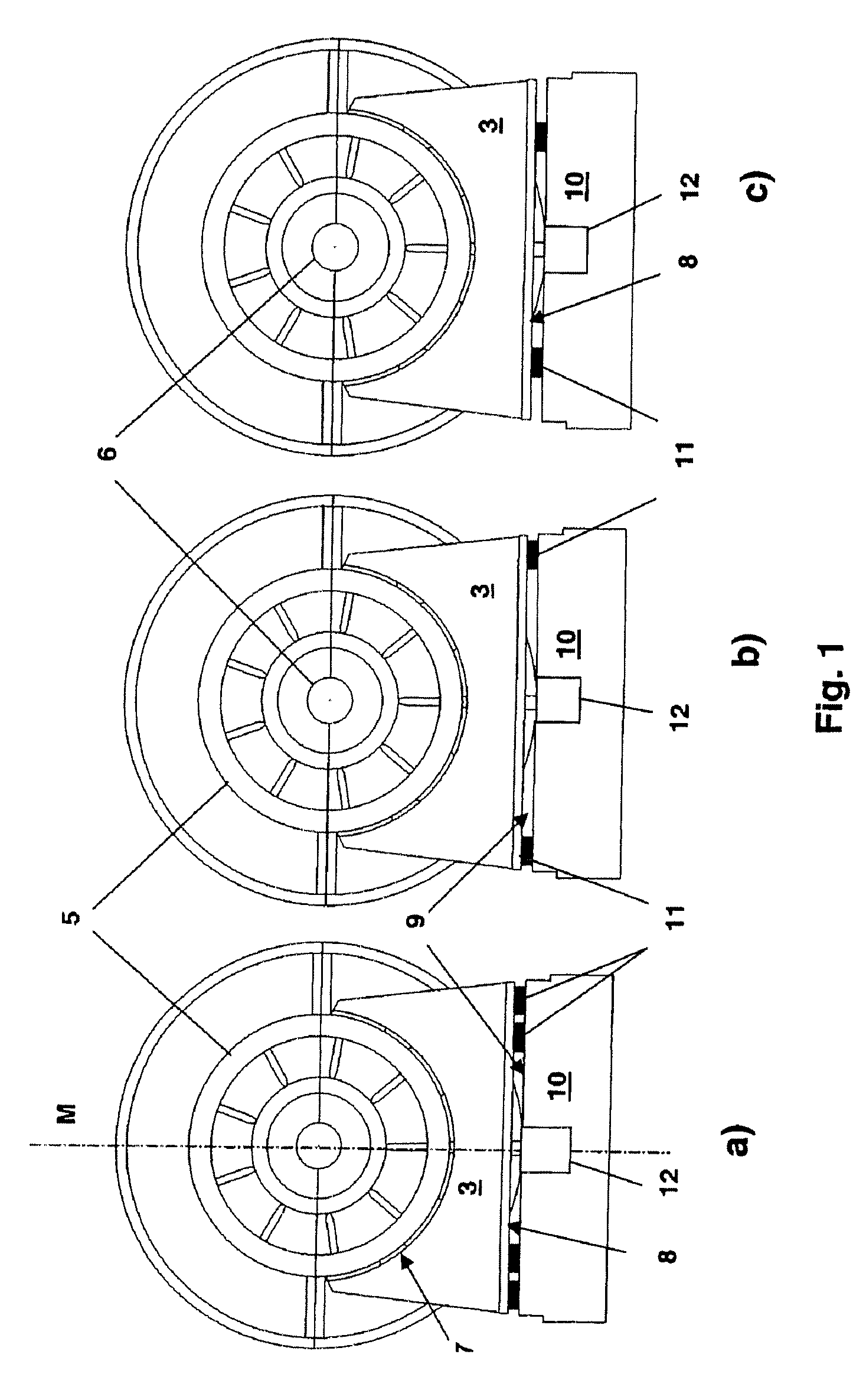
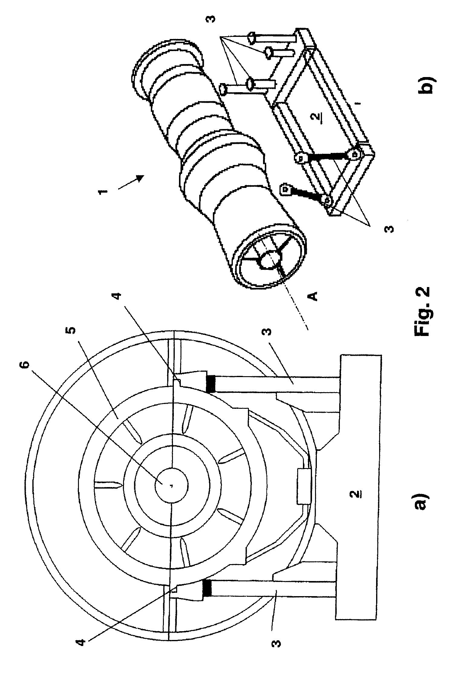
[0011]According to the disclosure, a device for mounting a turbine engine, e.g., a gas turbine system, has at least one support which provides at least one support face which is supported exclusively in partial regions on at least two support plate elements. At least one support face of the support is in operational engagement with the base frame by way of the support plate elements.

[0012]The disclosure makes it possible to make later adjustments to the mounting of a gas turbine system which is fully assembled on site, with the result that the vibration that is characteristic of an individual gas turbine system can be influenced in an effective manner, merely by a controlled arrangement of the so-called support plate elements, by way of which ultimately in certain parts the force of the weight of the entire gas turbine system acts on a supporting base frame. As the statements below, in particular those referring to the exemplary embodiment below, will show, the inherent elasticity w...


PUM


Abstract

A device and a method for mounting a turbine engine, e.g., a gas turbine system, are described, in which a rotor unit is mounted to rotate inside a stationary external housing, having at least two supports for taking up the weight of the turbine engine, these supports being arranged at a spacing from one another in an axial longitudinal direction in relation to the external housing and at one side being articulated directly or indirectly on the external housing and at the other being supported directly or indirectly on a base frame. At least one support provides at least one support face which is supported exclusively in partial regions on at least two support plate elements. The at least one support face of the support is in operational engagement with the base frame by way of the support plate elements.

Description

RELATED APPLICATIONS[0001]This application claims priority under 35 U.S.C. §119 to Swiss Application No. 00412 / 06 filed in Switzerland on Mar. 17, 2006, and as a continuation application under 35 U.S.C. §120 to PCT / EP2007 / 051649 filed as an International Application on Feb. 21, 2007 designating the U.S., the entire contents of which are hereby incorporated by reference in their entireties.TECHNICAL FIELD[0002]A device and a method are disclosed for mounting a turbine engine, e.g., a gas turbine system, in which a rotor unit is mounted to rotate inside a stationary external housing, having at least two supports for taking up the weight of the turbine engine, these supports being arranged at a spacing from one another in an axial longitudinal direction in relation to the external housing and at one side being articulated directly or indirectly on the external housing and at the other being supported directly or indirectly on a base.BACKGROUND INFORMATION[0003]Powerful gas turbine syst...

Claims


Application Information

Patent Timeline
Patent Type & Authority Applications(United States)
IPC IPC(8): F02C7/20F01D25/28
CPCF01D25/28F01D25/04
Inventor BUSEKROS, ARMINOMISORE, OLATUNDEWILHELM, THOMAS
Owner ANSALDO ENERGIA IP UK LTD
Why Eureka
Try Eureka