Machining process of ball head assembly

A processing technology and assembly technology, which is applied in the processing technology field of ball head assemblies, can solve problems such as ball head component failure and ball head falling off, and achieve the effects of reducing friction, facilitating universal rotation, and not easy to knead and deform

Active Publication Date: 2021-10-12
EXCELLENT FASTENING SYST SHANGHAI
View PDF6 Cites 0 Cited by
  • Summary
  • Abstract
  • Description
  • Claims
  • Application Information

AI Technical Summary

Problems solved by technology

[0003] In view of the above-mentioned related technologies, the inventor believes that during the use of the ball head assembly, the ball head is easy to fall off from the ball groove, making the ball head assembly invalid

Method used


Image

  • Machining process of ball head assembly
  • Machining process of ball head assembly
  • Machining process of ball head assembly

Examples


Embodiment Construction

[0048] The following is attached Figure 1-4 The present invention is described in further detail.

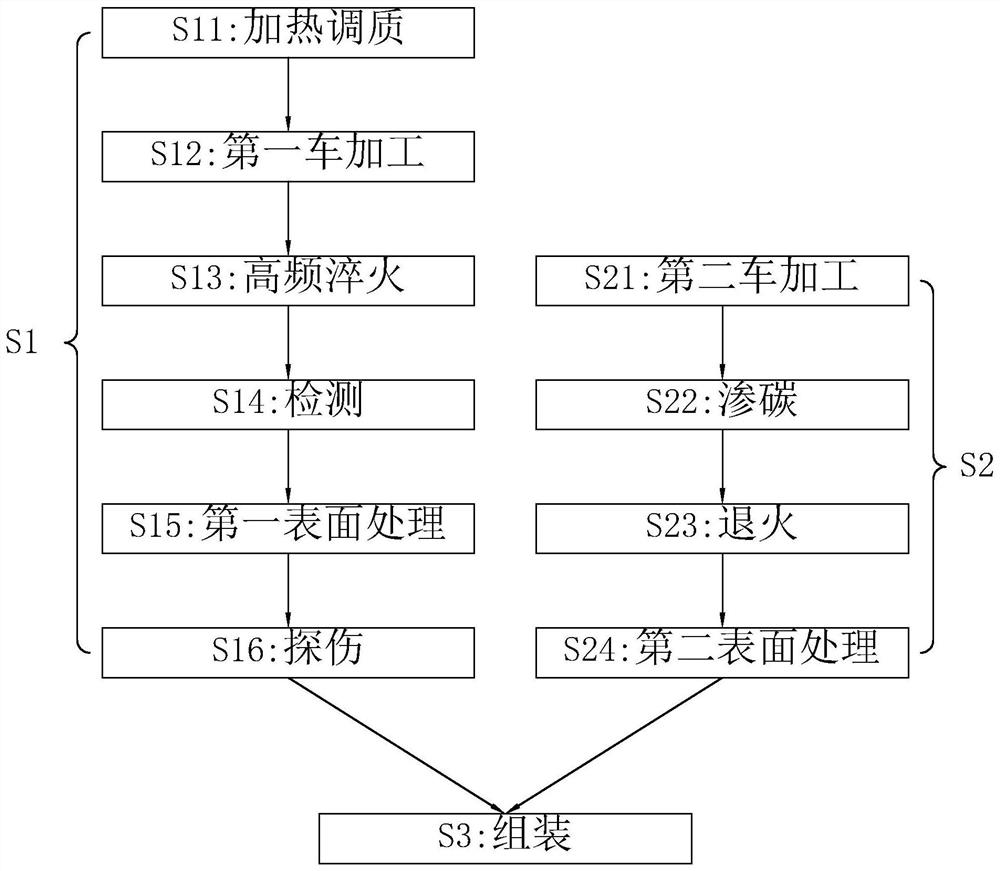
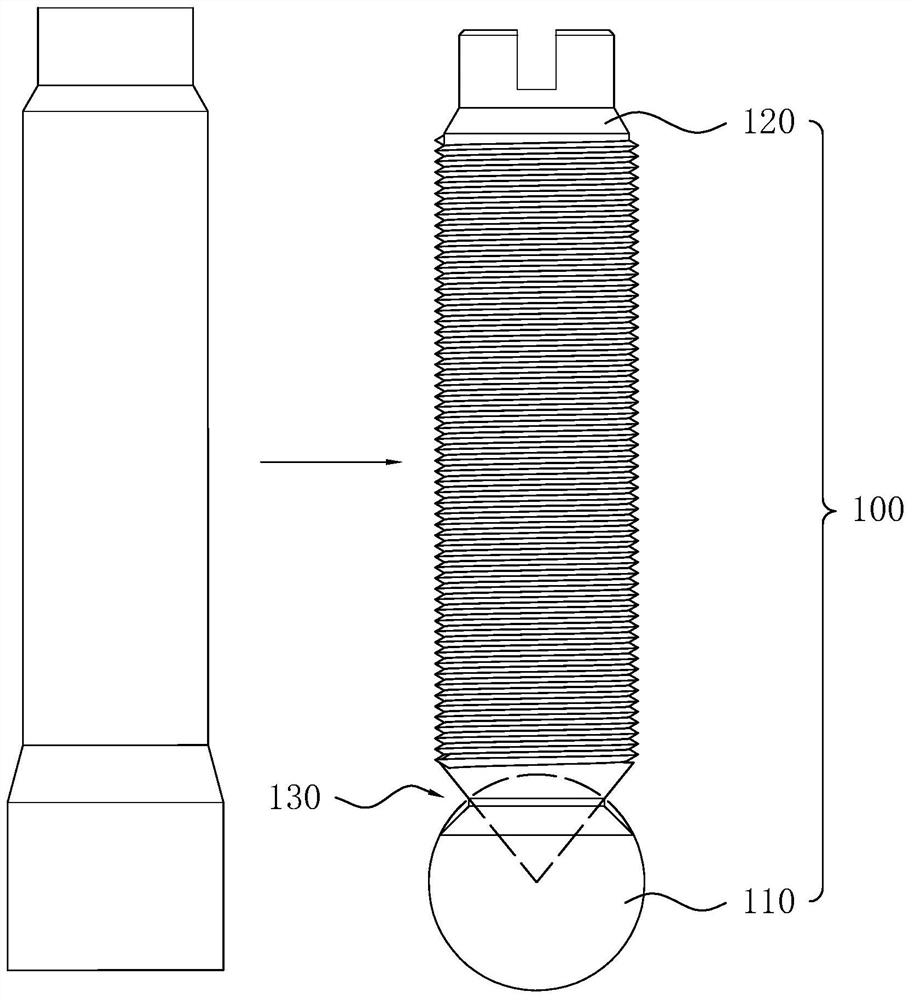
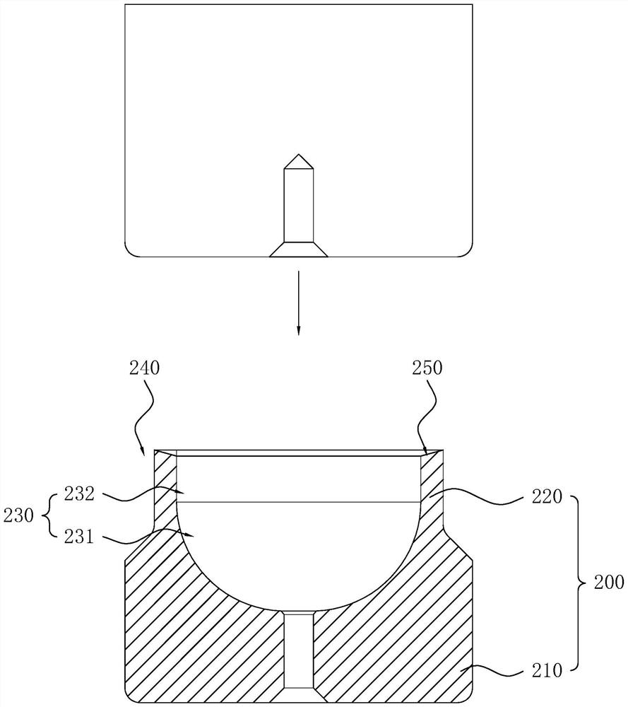
[0049] The embodiment of the present application discloses a processing technology of a ball head assembly. refer to figure 1 , the processing technology of the ball head assembly includes S1: the step of processing the ball head 100, S2: the step of processing the ball seat 200 and S3: the step of assembling; in the step of S1: processing the ball head 100, the blank is processed into The ball head rod 100 with the rod body 120 and the ball head 110; in S2: in the step of processing the ball seat 200, the blank is processed into the ball seat 200 with the ball groove 230; in S3: in the assembly step, the ball head rod 100 The ball head 110 is placed in the ball groove 230, and then the outer peripheral surface of the end of the ball seat 200 close to the ball groove 230 is squeezed, so that the end of the ball seat 200 close to the ball groove 230 shrinks toward the axis of ...


PUM

PropertyMeasurementUnit
hardnessaaaaaaaaaa
hardnessaaaaaaaaaa
hardnessaaaaaaaaaa

Abstract

The invention relates to the technical field of ball head assembly machining, in particular to a machining process of a ball head assembly. The machining process comprises the steps of machining a ball head rod, machining a ball seat and assembling, and the step of machining the ball head rod further comprises a first turning step and a high-frequency quenching step; the first turning step: cutting the blank to enable the blank to form a rod body and a ball head; and the high-frequency quenching step: carrying out high-frequency quenching on the rod body and the ball head, wherein the surface hardness of the quenched rod body and ball head is not smaller than HRC58, and the surface decarburization phenomenon of the rod body and ball head is not allowed. The surface hardness of the ball head rod can be improved, the probability of deformation of the ball head is reduced, and the probability that the ball head falls off from the ball groove to cause failure of the ball head assembly is reduced; and moreover, the ball head is not easy to rub and deform in the ball groove, so that the friction force of the ball head in the ball groove is reduced, the universal rotation of the ball head in the ball groove is facilitated, and the service life of the ball head assembly is prolonged.

Description

technical field [0001] The invention relates to the field of flange machining, in particular to a machining process of a ball head assembly. Background technique [0002] The ball head assembly mostly includes a ball seat and a ball head rod. The ball head rod includes a ball head and a rod body. The ball head is fixedly connected to one end of the rod body. A ball groove for accommodating the ball head is provided on the ball seat. When in use, the ball head is clamped in the ball groove, so that the ball head can be connected with the ball seat for universal rotation. [0003] With regard to the above-mentioned related technologies, the inventor believes that during the use of the ball head assembly, the ball head is easy to fall off from the ball groove, making the ball head assembly invalid. Contents of the invention [0004] In order to reduce the probability that the ball head falls out of the ball groove, the present invention provides a processing technology for t...

Claims


Application Information

Patent Timeline
Patent Type & Authority Applications(China)
IPC IPC(8): F16C11/06B23P15/00C21D1/10C21D1/18C21D1/25C21D1/26C21D9/00C23C8/00
CPCF16C11/0685F16C11/0695F16C11/0623B23P15/00C21D1/10C21D1/18C21D1/25C21D1/26C21D9/0068C23C8/00F16C2220/62F16C2223/18F16C2223/12F16C2223/10F16C2226/10B23P2700/11Y02P10/25
Inventor 刘亮江波仲朝江
Owner EXCELLENT FASTENING SYST SHANGHAI
Why Eureka
Try Eureka