Method and device for manufacturing efficient and high-precision composite additive

A manufacturing method and technology of a generating device are applied in the high-efficiency and high-precision composite material manufacturing method and device, and the high-efficiency and high-precision material manufacturing field to achieve the effects of improving surface quality, shortening forming time, and improving forming efficiency.

Active Publication Date: 2014-12-10
HUAZHONG UNIV OF SCI & TECH
View PDF7 Cites 38 Cited by
  • Summary
  • Abstract
  • Description
  • Claims
  • Application Information

AI Technical Summary

Problems solved by technology

[0006] In order to solve the problems of low forming efficiency and poor surface quality in the above-mentioned single high-energy beam additive manufacturing, the present invention provides a high-efficiency and high-precision additive manufacturing method in which laser beams and electron beams are combined, in order to take advantage of th

Method used


Image

  • Method and device for manufacturing efficient and high-precision composite additive
  • Method and device for manufacturing efficient and high-precision composite additive
  • Method and device for manufacturing efficient and high-precision composite additive

Examples


example 1

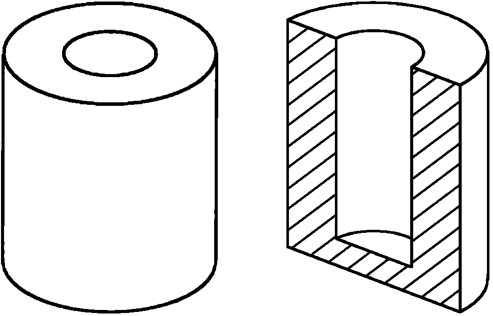
[0040] (1) Put image 3 The surface profile and internal structure of the model shown are divided into three regions, S1, S2, and S3 ( Figure 4 ), control the working range of laser beam and electron beam. The material used is spherical 316L stainless steel powder with a particle size of about 10-100μm.

[0041] (2) Set the powder spreading layer thickness of the device to 0.02mm, SLM scanning single layer powder thickness to 0.02mm, EBM scanning single layer powder thickness to 0.08mm. The forming space of the device is evacuated and a protective gas is introduced.

[0042] (3) A layer of powder is spread on the metal substrate by the powder spreading mechanism, and the thin layer of powder in the S1 area is scanned at a high speed by the small beam current of the electron beam to preheat the powder.

[0043] (4) Control the laser beam generating device to move to the scanning window, the laser beam scans the powder in the S1 area to form a surface contour layer, and the electron...

example 2

[0048] (1) Put image 3 The surface profile and internal structure of the model shown are divided into three regions, S1, S2, and S3 ( Figure 4 ), control the working range of laser beam and electron beam. The material used is spherical Ti6Al4V powder with a particle size of about 10-100μm.

[0049] (2) The thickness of the powder spreading layer of the setting device is 0.02mm, the thickness of the single-layer powder scanned by SLM is 0.02mm, and the thickness of single-layer powder scanned by EBM is 0.5mm. The forming space of the device is evacuated and a protective gas is introduced.

[0050] (3) A layer of powder is spread on the metal substrate by the powder spreading mechanism, and the thin layer of powder in the S1 area is scanned at a high speed by the small beam current of the electron beam to preheat the powder.

[0051] (4) Control the laser beam generating device to move to the scanning window, the laser beam scans the powder in the S1 area to form a surface contour ...


PUM

PropertyMeasurementUnit
Particle sizeaaaaaaaaaa

Abstract

The invention discloses a method and device for manufacturing efficient and high-precision composite additive, and the method and device are achieved through composition of a laser beam and an electron beam. In the process of the action of a high energy beam and metal powder, metal powder of a surface outline is scanned and molten through the laser beam, and the surface of a part has a good surface quality. The electron beam melts the internal powder at a high speed to form a part inner cavity so as to reach the highest forming efficiency. The lower portion of the device comprises a powder laying roller, a workbench, a powder conveying cylinder and a working cylinder. The upper portion of the device comprises an electron beam generating device, a laser beam generating device, a bottom plate, two guide rails, two beams, a synchronous belt wheel and a servo motor. The electron beam generating device and the laser beam generating device are respectively integral and move to the forming area alternately to carry out scanning. By means of the method and device, the defects in the single forming technology can be overcome, and the purposes of reasonably controlling the formed microstructural organization and optimizing the comprehensive performance are achieved.

Description

Technical field [0001] The invention belongs to the field of advanced manufacturing technology, and is a high-efficiency and high-precision composite material manufacturing method and device. The invention adopts two kinds of high-energy beams for composite additive manufacturing, especially the high-efficiency and high-precision manufacturing of laser beams and electron beams. The invention comprehensively utilizes the advantages of high laser beam forming precision and fast electron beam forming speed, and organically combines the two. Background technique [0002] High-energy beams mainly include laser beams, electron beams and ion beams. The high-energy beam molten metal powder manufacturing technology is an advanced technology developed in recent years that can realize the manufacturing of nearly dense metal parts and materials. In the computer, the three-dimensional graphics of the parts to be manufactured are divided into a series of two-dimensional graphics slices, and ...

Claims


Application Information

Patent Timeline
IPC IPC(8): B22F3/105
CPCY02P10/25
Inventor 魏青松史玉升韩昌骏李帅唐萍刘洁
Owner HUAZHONG UNIV OF SCI & TECH
Why Eureka
Try Eureka