Spiral pipe robot

A pipeline robot, spiral technology, applied in the direction of special pipes, pipe components, mechanical equipment, etc., can solve the problems of drive wheel stuck, affect the reliability of pipeline robot operation, and cannot ensure the smooth operation of the robot, so as to ensure the convenience Effect

Active Publication Date: 2015-11-18
无锡普瑞精密技术有限公司
View PDF6 Cites 2 Cited by
  • Summary
  • Abstract
  • Description
  • Claims
  • Application Information

AI Technical Summary

Problems solved by technology

There are helical pipeline robots used in different situations in the prior art, but these pipeline robots still have the following defects: First, the pipeline robot using a single driving wheel cannot ensure that its helical surface is always parallel to the pipeline section, and cannot ensure that the robot runs When the pipeline robot with two-wheel design encounters obstacles in the pipeline, although its helical surface is generally parallel to the pipeline section, there is still a phenomenon that the driving wheels are stuck; second, the adaptability to changes in the pipeline section On the one hand, there is an adjustment mechanism controlled by a telescopic rod and a single spring in the prior art. Although this adjustment mechanism can make the pipeline robot adapt to the change of the pipeline section, the adaptability is limited. When the diameter of the pipeline section changes greatly, the adjustment The elastic pressure generated by the mechanism cannot be controlled within a certain range. When the elastic pressure is large, the driving torque will be insufficient and the driving wheel will be stuck, which will affect the operational reliability of the pipeline robot.

Method used


Image

  • Spiral pipe robot
  • Spiral pipe robot
  • Spiral pipe robot

Examples


Embodiment Construction

[0038] The specific implementation manner of the present invention will be described below in conjunction with the accompanying drawings.

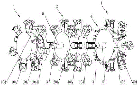
[0039] See figure 1 , the present invention includes symmetrically arranged travel assemblies 1, a control assembly 2 is arranged between two sets of travel assemblies 1, and the travel assembly 1 and control assembly 2 are connected by telescopic joints 5 and universal joints 3.

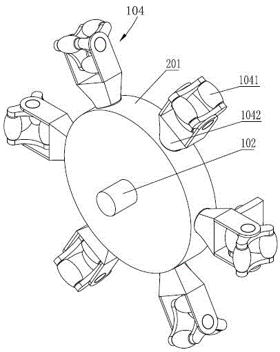
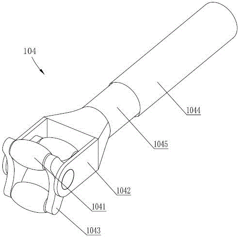
[0040] See figure 1 , figure 2 , the structure of the walking assembly 1 is as follows: including the mounting frame 101, the mounting frame 101 is provided with a motor one 102, the output shaft of the motor one 102 is connected with the rotating frame 103 through a coupling, and the mounting frame 101 and the rotating frame 103 are evenly arranged along the circumference There are a plurality of roller mechanisms 104, and the roller mechanisms 104 of the mounting frame 101 and the roller mechanisms 104 of the rotating frame 103 are arranged in a staggered m...


PUM


Abstract

A spiral type pipeline robot comprises walking assemblies which are symmetrically arranged, wherein a control assembly is arranged between the two walking assemblies which are connected with the control assembly through telescopic joints and universal joints. As for the walking assemblies, a motor in an installation frame drives a rotary fame so as to drive a driving idler wheel mechanism on the rotary frame to move forwards in a spiral mode, and both the walking assemblies and the control assembly are provided with guide idler wheel mechanisms. Each idler wheel mechanism is sleeved with a sleeve through an elastic supporting arm, a plurality of external spring channels and inner spring channels are arranged in the elastic supporting arm, the depths of the external spring channels and the depths of the inner spring channels are increased sequentially, the external spring channels are used for compressing and releasing springs fixed at the bottom of the sleeve, the inner spring channels are provided with sealed space with adjustable pressure, and the pressure of the sealed space is adjusted through a one-way pressure relief opening. The spiral type pipeline robot can effectively adapt to changes of inner diameters of pipelines, effectively pass over small barriers, completely and reliably detect the pipelines, and move flexibly, stably and reliably.

Description

technical field [0001] The invention relates to an industrial pipeline detection robot, in particular to a spiral pipeline robot. Background technique [0002] Industrial piping systems have been widely used in the fields of metallurgy, petroleum, chemical industry, and urban water heating supply. The working environment of industrial piping is very harsh. After long-term use, it is prone to corrosion, fatigue damage, or potential internal defects of the piping develop into damage and cause leakage accidents, etc. . Therefore, the in-pipe detection of pipelines is a very important practical project, which is related to the safe and efficient operation of various pipelines. At present, in-pipe detection is mostly carried out by pipeline robots. Since the pipeline robot is subject to strong pipeline constraints in the pipeline, especially when encountering a curved pipeline, on the one hand, the robot needs enough friction to overcome the influence of gravity when walking in ...

Claims


Application Information

Patent Timeline
Patent Type & Authority Patents(China)
IPC IPC(8): F16L55/32F16L101/30
CPCF16L55/32
Inventor 周德强陆赛浩吴佳龙尤丽华李建海张秋菊
Owner 无锡普瑞精密技术有限公司
Why Eureka
Try Eureka