Energy-consuming-type rotatable ship collision preventing device with fin plates

A technology of anti-ship collision and fin plate, which is applied to bridge parts, climate change adaptation, bridges, etc., can solve the problems of easy damage, difficult repair and high cost of anti-collision facilities

Active Publication Date: 2014-04-02
NANJING UNIV OF TECH
View PDF5 Cites 12 Cited by
  • Summary
  • Abstract
  • Description
  • Claims
  • Application Information

AI Technical Summary

Problems solved by technology

[0004] The purpose of the present invention is to provide a rotatable anti-ship with finned plate energy consumption type for the problems of poor anti-collision effect, easy damage of anti-collision facilities, high cost or difficult repair existing in existing bridge anti-collision devices. Collision device, which can effectively absorb the kinetic energy of the ship in trouble, has a greater anti-collision capability, and plays an effective role in safety protection for bridges, waterways and water facilities, and is easy to install, construct, and maintain.

Method used


Image

  • Energy-consuming-type rotatable ship collision preventing device with fin plates
  • Energy-consuming-type rotatable ship collision preventing device with fin plates
  • Energy-consuming-type rotatable ship collision preventing device with fin plates

Examples


Embodiment 1

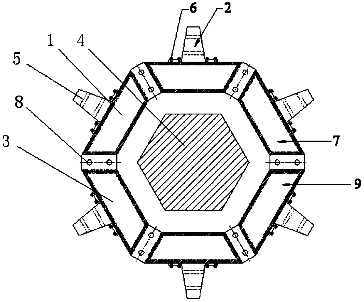
[0028] Such as figure 1 As shown, a rotatable anti-ship collision device with finned plate energy consumption type, the anti-ship collision device 1 floats on the water surface, and is arranged around the periphery of the pier 4 on the channel, and the anti-ship collision device 1 is designed to be able to wrap around the pier 4 rotating device;

[0029] The anti-collision device 1 includes anti-collision fins 2 and anti-collision rings 3, the anti-collision fins 2 are multiple, and are evenly arranged around the anti-collision rings 3, and the anti-collision fins 2 pass through The fastener 6 is installed on the anti-collision ring 3, or the anti-collision fin plate 2 and the anti-collision ring 3 are integrally formed.

[0030] The shape of the anti-collision ring 3 is adapted to the shape of the pier 4, and the shape of the pier 4 is hexagonal, and the shape of the corresponding anti-collision ring 3 is also hexagonal. The anti-collision fins 2 and the anti-collision ring...

Embodiment 2

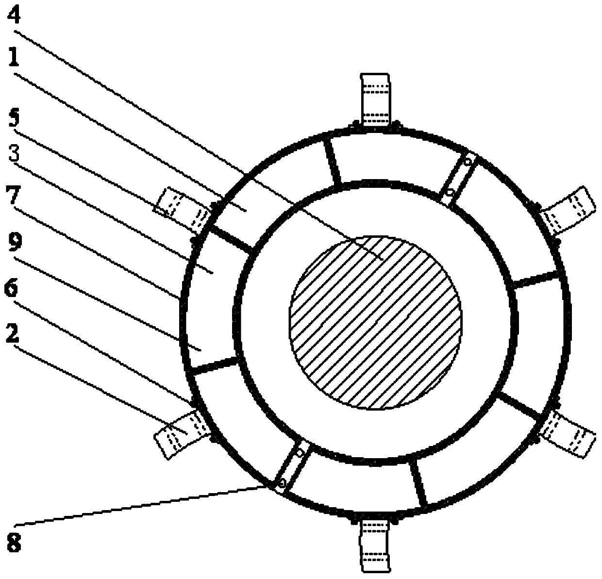
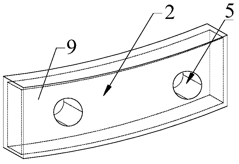
[0032] Such as figure 2 , 3 As shown in and 4, the difference between this embodiment and embodiment 1 is that the shape of the pier 4 is circular, and the shape of the corresponding anti-collision ring 3 is also circular. The anti-collision fins 2 are strip-shaped, and the water-facing surface of the anti-collision fins 2 is arc-shaped. The anti-collision fins 2 are arranged around the anti-collision ring 3 in multiple layers.

[0033] working principle:

[0034] When the ship in trouble is on the side of the channel and sails directly to the bridge pier 4 of the channel, the anti-collision ring 3 arranged on the anti-ship collision device 1 around the bridge pier blocks the ship in trouble, and the anti-collision ring 3 absorbs the impact energy of the part of the ship in trouble. The ship causing the accident with huge kinetic energy contacts the anti-collision fin plate 2 and pushes the anti-collision fin plate 2. At this time, the anti-collision fin plate 2 drives the...


PUM


Abstract

The invention discloses an energy-consuming-type rotatable ship collision preventing device with fin plates. The ship collision preventing device floats on the water, is arranged around a bridge pier on a shipping lane, is a device capable of rotating around the bridge pier and comprises multiple collision preventing fin plates and a collision preventing ring, the collision preventing fin plates are uniformly arranged around the collision preventing ring and mounted on the collision preventing ring through fastening members, or the collision preventing fin plates and the collision preventing ring are of an integrally-formed structure. The energy-consuming-type rotatable ship collision preventing device can effectively absorb kinetic energy of an offending ship, has high collision preventing capability, plays a role in effectively protecting safety of a bridge, the shipping lane and water-based facilities and is easy to mount, construct, repair and maintain.

Description

technical field [0001] The invention relates to an anti-collision protection technology for bridges, waterways and water facilities. The ship collision device can be used for anti-collision protection of waterways and water facilities. Background technique [0002] As we all know, ship collision accidents have been happening all over the world, and the frequency of ship collision accidents is much higher than we imagined. The loss of life, property damage, and environmental damage caused by ship-bridge accidents is staggering. Many ship collision accidents range from losses of tens of thousands of yuan to casualties, losses in millions, tens of millions or even billions of dollars, and a large number of indirect losses are even more difficult to calculate. Therefore, it is particularly necessary to take anti-collision measures for bridges. The fundamental purpose is to prevent structural damage of bridges due to ship impact, and at the same time protect ships as much as po...

Claims


Application Information

Patent Timeline
Patent Type & Authority Applications(China)
IPC IPC(8): E02B3/26E01D19/02
CPCY02A30/30
Inventor 刘伟庆孙慧明方海祝露
Owner NANJING UNIV OF TECH
Why Eureka
Try Eureka