Loop uhf near field rfid reader antenna

A reader and antenna technology, which is applied in the field of annular ultra-high frequency (UHF) near-field RFID reader/writer antennas, can solve problems such as large size, and achieve the effects of low far-field gain, easy processing, and reduced interference.

Inactive Publication Date: 2016-06-29
SOUTH CHINA UNIV OF TECH
View PDF5 Cites 2 Cited by
  • Summary
  • Abstract
  • Description
  • Claims
  • Application Information

AI Technical Summary

Problems solved by technology

[0004] The present invention proposes a ring-shaped UHF near-field RFID reader-writer antenna in order to overcome the disadvantage that the electric large near-field antenna cannot be used for mobile portable devices due to its large volume and to adapt to the characteristics of low power consumption of handheld devices.

Method used


Image

  • Loop uhf near field rfid reader antenna
  • Loop uhf near field rfid reader antenna
  • Loop uhf near field rfid reader antenna

Examples


Embodiment Construction

[0020] specific implementation plan

[0021] The specific implementation process of the present invention will be described in detail below in conjunction with the accompanying drawings, but the protection scope of the present invention is not limited to the scope described in the following examples.

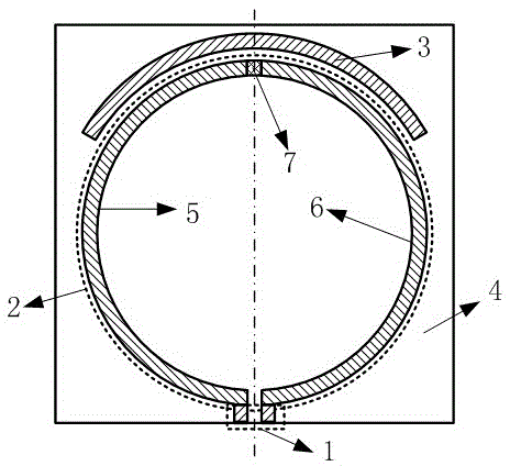
[0022] refer to figure 1 , the annular UHF near-field RFID reader antenna of the present invention is composed of a feed port 1, an annular structure 2, a parasitic arc-shaped patch 3 and a dielectric substrate 4; the annular structure is composed of a first arc-shaped patch 5, a second arc-shaped patch Composed of patch 6 and matching resistor 7; one end of the first arc-shaped patch 5 is connected to the feed port 1, and the other end is connected to one end of the matching resistor 7; the other end of the matching resistor 7 is connected to one end of the second arc-shaped patch 6 . The other end of the second arc patch 6 is connected to the feed port 1; the parasitic arc p...


PUM


Abstract

The invention discloses an annular UHF near-field RFID reader-writer antenna which has a plane structure. The antenna comprises a feed port, an annular structure, a parasitic arc-shaped SMD and a medium substrate. The annular structure is composed of a first arc-shaped SMD, a second arc-shaped SMD and a matching resistor. One end of the first arc-shaped SMD is connected with the feed port, and the other end is connected with the matching resistor. The other end of the matching resistor is connected with one end of the second arc-shaped SMD. The other end of the second arc-shaped SMD is connected with the feed port. The parasitic arc-shaped SMD is arranged outside the annular structure, and the distance between the internal edge of the parasitic arc-shaped SMD and the external edge of the annular structure is same at all parts. The annular structure, the parasitic arc-shaped SMD and the feed port are all arranged on the same surface of the medium substrate. The whole antenna is symmetrical relative to the central axis of the antenna. The annular UHF near-field RFID reader-writer antenna has characteristics of being high in near-field magnetic field intensity, low in far-field gain, small in size, convenient to process and manufacture, low in cost, etc. , so that the annular UHF near-field RFID reader-writer antenna is suitable for various ultrahigh frequency near-field RFID systems and especially suitable for ultralow power consumption hand-held devices.

Description

technical field [0001] The invention relates to a near-field radio frequency identification (RFID) reader-writer antenna, in particular to an annular ultra-high frequency (UHF) near-field RFID reader-writer antenna. Background technique [0002] Radio frequency identification (RFID) technology is an automatic identification technology that conducts non-contact two-way data communication through radio frequency to identify targets and obtain relevant information. The working frequency of RFID includes low frequency (135KHz), high frequency (13.56MHz), ultrahigh frequency (860-960MHz) and microwave frequency band (above 2.4GHz), among which high frequency and ultrahigh frequency are the most widely used. The reader antenna plays an irreplaceable role in the radio frequency identification system. In recent years, with the introduction of item-level RFID applications, more and more attention has been paid to UHF RFID systems using near-field coupling. UHF near-field RFID syste...

Claims


Application Information

Patent Timeline
Patent Type & Authority Patents(China)
IPC IPC(8): H01Q1/38
Inventor 胡斌杰腾潢龙魏晓东
Owner SOUTH CHINA UNIV OF TECH
Why Eureka
Try Eureka