rear trailing arm

A technology of rear trailing arm and body, which is applied to the cantilever mounted on the pivot, suspension, transportation and packaging, etc., can solve the problems of complex structure of the rear trailing arm, simplify the structure and processing procedures, and reduce welding deformation. The effect of improving the positioning accuracy

Active Publication Date: 2016-05-18
CHERY AUTOMOBILE CO LTD
View PDF9 Cites 0 Cited by
  • Summary
  • Abstract
  • Description
  • Claims
  • Application Information

AI Technical Summary

Problems solved by technology

[0006] In order to solve the problem of complex structure of the rear trailing arm in the prior art, the embodiment of the present invention provides a rear trailing arm

Method used


Image

  • rear trailing arm
  • rear trailing arm

Examples


Embodiment 1

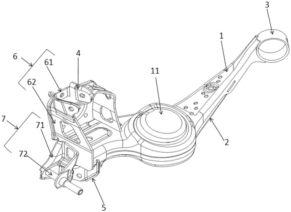
[0040] as attached figure 1 As shown, the embodiment of the present invention provides a rear trailing arm, including: upper body 1, lower body 2, bushing 3, upper swing arm connection seat 4, lower swing arm connection seat 5, brake mounting platform 6 and shock absorber mounting table 7,

[0041] Both the upper body 1 and the lower body 2 are stamped and formed by a single-layer steel plate;

[0042] The middle part of the upper body 1 is provided with a convex circular platform 11 upwards, the upper body 1 and the lower body 2 cooperate to form a cavity, and the two ends of the cavity are respectively a first end and a second end ;

[0043] The sleeve 3 is arranged at the first end of the cavity;

[0044] The brake mounting table 6 is arranged at the second end of the cavity;

[0045] The upper swing arm connecting seat 4 is arranged on the upper part of the brake mounting table 6;

[0046] The lower swing arm connecting seat 5 is arranged at the lower part of the seco...

Embodiment 2

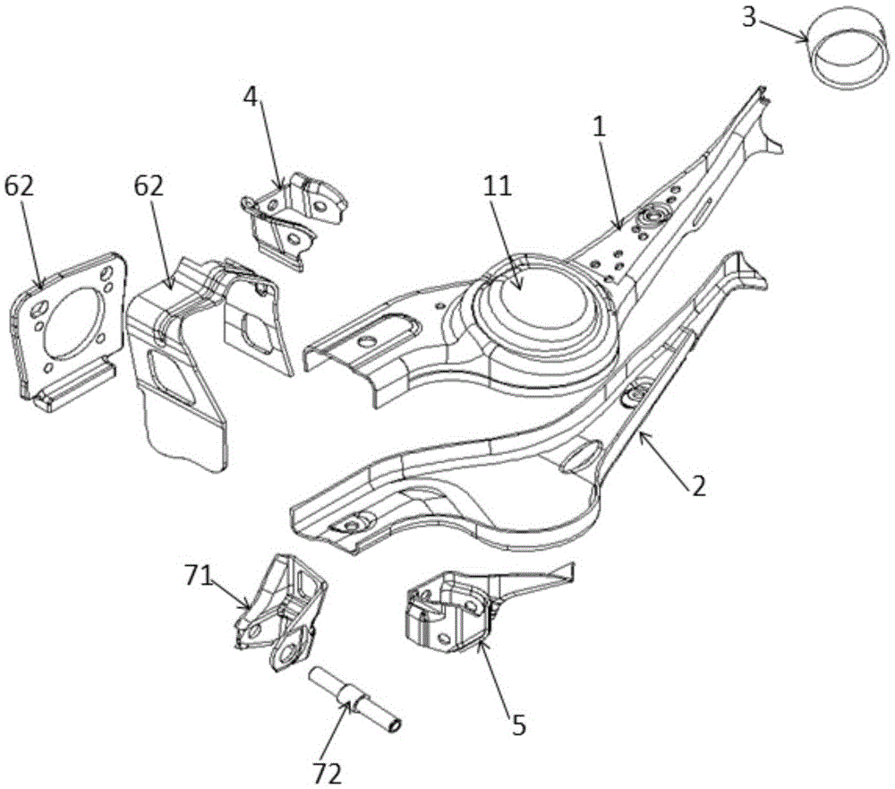
[0070] The embodiment of the present invention provides a rear trailing arm, which includes: an upper body 1, a lower body 2, a bushing 3, an upper swing arm connection seat 4, a lower swing arm connection seat 5, a brake mounting platform 6, a Vibrator mounting table 7;

[0071] Wherein, both the upper body 1 and the lower body 2 are stamped and formed by single-layer steel plates, and cooperate with each other to form a square cavity support structure, and the middle part of the upper body 1 is provided with a convex round table with guiding threads facing upwards. 11;

[0072] The casing 3 is arranged at the first end of the cavity, and the first end is set in a rock axially concave shape, so as to facilitate the fixing of the casing 3;

[0073] The brake mounting table 6 is arranged at the second end of the cavity,

[0074] Specifically, the brake mounting table 6 includes: a brake mounting outer plate and a brake mounting inner plate, and the brake mounting outer plate ...


PUM


Abstract

The invention discloses a rear trailing arm, which belongs to the technical field of automobile rear suspension. The rear trailing arm includes: an upper body, a lower body, a bushing, an upper swing arm connecting seat, a lower swing arm connecting seat, a brake mounting platform and a shock absorber mounting platform. By matching the upper body and the lower body formed by stamping a single-layer steel plate into a cavity, the overall strength of the rear trailing arm can be greatly improved, and the use of reinforcement plates can be reduced or avoided; and the first end of the cavity is stamped It can avoid the use of the transition arm by forming a suitable shape to directly connect with the bushing; thus, the rear trailing arm structure provided by the embodiment of the present invention can simplify the structure and processing procedures while ensuring the practical strength; and due to the stamping process The use of the invention and the simplification of the structure of the present invention greatly reduce the overall number of welding parts, thereby reducing the welding deformation of the rear trailing arm during the welding process, thereby improving the positioning accuracy of each joint of the rear trailing arm.

Description

technical field [0001] The invention relates to the technical field of automobile rear suspension, in particular to a rear trailing arm. Background technique [0002] The rear trailing arm is a commonly used connector for the rear suspension of a car. It can be longitudinally connected between the body and the rear wheels through the connection with the upper swing arm and the lower swing arm, so as to support the body and act on the road surface on the wheels. The purpose of force transmission to the body is to ensure the normal driving of the car; through the connection of hydraulic shock absorbers and coil springs, the purpose of shock absorption of the body is achieved. [0003] At present, the rear trailing arm generally includes: an upper body, a lower body, an upper swing arm connecting seat, a lower swing arm connecting seat, a shock absorber mounting platform, a bushing, a transition arm and a plurality of reinforcing plates. The upper body and the lower body coope...

Claims


Application Information

Patent Timeline
Patent Type & Authority Patents(China)
IPC IPC(8): B60G7/00
Inventor 杨展蔡其刚
Owner CHERY AUTOMOBILE CO LTD
Why Eureka
Try Eureka