Coal distribution device

A technology of falling coal and inclined tubes, which is applied in the field of circulating fluidized bed boilers, can solve the problems of accelerating the flow speed of coal material, easy backflow of flue gas, long conveying distance, etc., and achieve the effect of increasing dynamic pressure

Active Publication Date: 2014-07-30
HMEI THREAD CO LTD OF YINBIN SICHUAN +1
View PDF8 Cites 5 Cited by
  • Summary
  • Abstract
  • Description
  • Claims
  • Application Information

AI Technical Summary

Problems solved by technology

In the coal feeding device disclosed in this patent document, the sealing air chamber and the sealing air nozzle are arranged at the entrance of the coal-feeding pipe. Weakening directly causes the air pressure of the sealing air to be insufficient to offset the positive pressure from the flue gas in the furnace, and the coal sowing air chamber and the coal sowing air nozzle are set at the coal feeding nozzle. It is not the same, most of the coal sowing wind blows the coal mate

Method used


Image

  • Coal distribution device
  • Coal distribution device
  • Coal distribution device

Examples


Embodiment 1

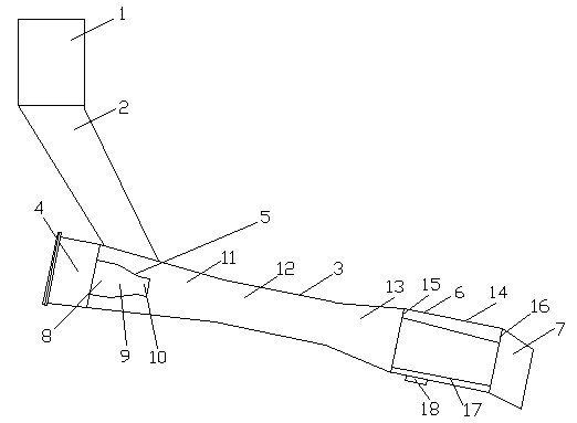
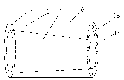
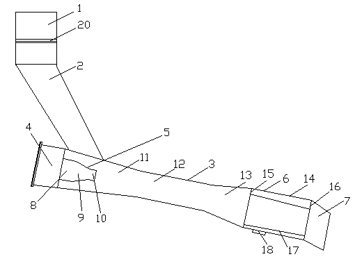
[0056] A coal sowing device, comprising a straight coal drop pipe 1, a first inclined coal drop pipe 2, a second inclined coal drop pipe 3, a static pressure sealed air chamber 4, a sealed air nozzle 5, a coal broadcast air chamber 6 and a sowing The coal outlet 7, the coal falling straight pipe 1 communicates with the second coal falling inclined pipe 3 through the first coal falling inclined pipe 2, the static pressure sealing air chamber 4 is connected with one end of the second coal falling inclined pipe 3, the second coal falling inclined pipe The other end of the pipe 3 communicates with the coal sowing port 7 through the coal sowing air chamber 6, the sealing air nozzle 5 is located in the second coal falling inclined pipe 3, the first coal falling inclined pipe 2 is in the shape of a truncated cone, and the first coal falling inclined The area of ​​the upper bottom surface of the pipe 2 is larger than the area of ​​the lower bottom surface. The sealing air nozzle 5 is s...

Embodiment 2

[0060] A coal sowing device, comprising a straight coal drop pipe 1, a first inclined coal drop pipe 2, a second inclined coal drop pipe 3, a static pressure sealed air chamber 4, a sealed air nozzle 5, a coal broadcast air chamber 6 and a sowing The coal outlet 7, the coal falling straight pipe 1 communicates with the second coal falling inclined pipe 3 through the first coal falling inclined pipe 2, the static pressure sealing air chamber 4 is connected with one end of the second coal falling inclined pipe 3, the second coal falling inclined pipe The other end of the pipe 3 communicates with the coal sowing port 7 through the coal sowing air chamber 6, the sealing air nozzle 5 is located in the second coal falling inclined pipe 3, the first coal falling inclined pipe 2 is in the shape of a truncated cone, and the first coal falling inclined The area of ​​the upper bottom surface of the pipe 2 is larger than the area of ​​the lower bottom surface. The sealing air nozzle 5 is s...

Embodiment 3

[0065]A coal sowing device, comprising a straight coal drop pipe 1, a first inclined coal drop pipe 2, a second inclined coal drop pipe 3, a static pressure sealed air chamber 4, a sealed air nozzle 5, a coal broadcast air chamber 6 and a sowing The coal outlet 7, the coal falling straight pipe 1 communicates with the second coal falling inclined pipe 3 through the first coal falling inclined pipe 2, the static pressure sealing air chamber 4 is connected with one end of the second coal falling inclined pipe 3, the second coal falling inclined pipe The other end of the pipe 3 communicates with the coal sowing port 7 through the coal sowing air chamber 6, the sealing air nozzle 5 is located in the second coal falling inclined pipe 3, the first coal falling inclined pipe 2 is in the shape of a truncated cone, and the first coal falling inclined The area of ​​the upper bottom surface of the pipe 2 is larger than the area of ​​the lower bottom surface. The sealing air nozzle 5 is se...


PUM


Abstract

The invention discloses a coal distribution device, which comprises a coal dropping straight pipe, a first coal dropping inclined pipe, a second coal dropping inclined pipe, a hydrostatic sealing air chamber, a sealing air nozzle, a coal distribution air chamber and a coal distribution opening, wherein the first coal dropping inclined pipe takes the shape of a circular truncated cone; the sealing air nozzle is integrally formed by a large cylindrical pipe, a circular truncated cone pipe and a small cylindrical pipe in sequence; the second coal dropping inclined pipe is integrally formed by a shrinkage section, a throat section and an expansion section; the coal distribution air chamber is composed of a cylinder body, a first eccentric ring end plate, a second eccentric ring end plate and a circular truncated cone-shaped coal distribution pipe; a coal distribution inlet is formed in the bottom of the cylinder body; coal distribution nozzles are distributed in the second eccentric ring end plate; the large cylindrical pipe is communicated with the air outlet end of the hydrostatic sealing air chamber; the first eccentric ring end plate is connected with the expansion section and the second eccentric ring end plate is connected with the coal distribution opening. By improving the coal distribution structure, the air pressure of the sealing air can be strengthened; the positive pressure of smoke from a hearth is counteracted by matching the air pressure of coal distribution air with that of the sealing air, so that the smoke is prevented from jumping backwards and the environmental-friendly effect is improved.

Description

technical field [0001] The invention relates to the technical field of circulating fluidized bed boilers, in particular to a coal sowing device used in circulating fluidized bed boilers, which can effectively prevent flue gas from flowing back in the furnace. Background technique [0002] Circulating fluidized bed boiler is developed on the basis of bubbling bed boiler fluidized furnace, so some theories and concepts of bubbling bed can be used in circulating fluidized bed boiler. But there is a big difference. The early circulating fluidized bed boiler had a relatively high fluidization velocity, so it was called a fast circulating fluidized bed boiler. The basic theory of fast circulating bed boiler can also be used in circulating fluidized bed boiler. [0003] The circulating fluidized bed boiler can be divided into two parts: the first part is composed of the furnace, namely the fast fluidized bed, gas-solid separator, solid material recirculation equipment and externa...

Claims


Application Information

Patent Timeline
IPC IPC(8): F23C10/22
Inventor 张西平陈效肖雪峰
Owner HMEI THREAD CO LTD OF YINBIN SICHUAN
Why Eureka
Try Eureka