A ball bearing with a self-measuring system

A ball bearing, self-measurement technology, applied in the direction of bearing components, shafts and bearings, bearing assembly, etc., can solve the problems of difficulty in obtaining the running state of the bearing in a timely and accurate manner, non-real-time and other problems, achieve reasonable determination of configuration parameters, improve reliability, Structured novel effect

Inactive Publication Date: 2016-05-11
ZHEJIANG NORMAL UNIVERSITY
View PDF6 Cites 0 Cited by
  • Summary
  • Abstract
  • Description
  • Claims
  • Application Information

AI Technical Summary

Problems solved by technology

[0003] The present invention provides a ball bearing with a self-measurement system to solve the problem that existing bearing monitoring systems in practical applications are all non-real-time, indirect non-contact measurement, and it is difficult to obtain the running state of the bearing in time and accurately

Method used


Image

  • A ball bearing with a self-measuring system
  • A ball bearing with a self-measuring system
  • A ball bearing with a self-measuring system

Examples


Embodiment Construction

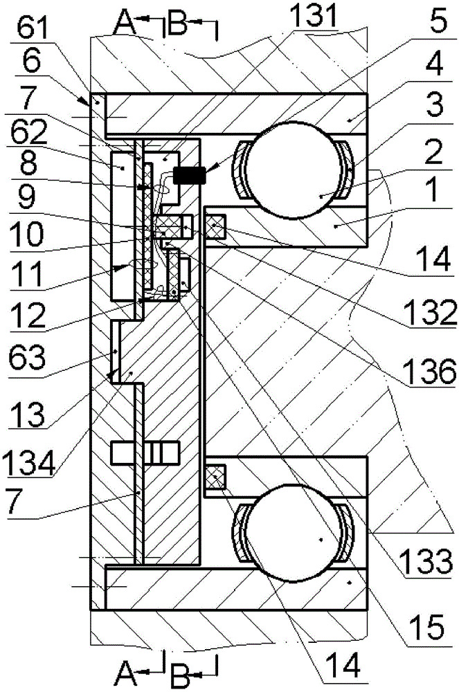
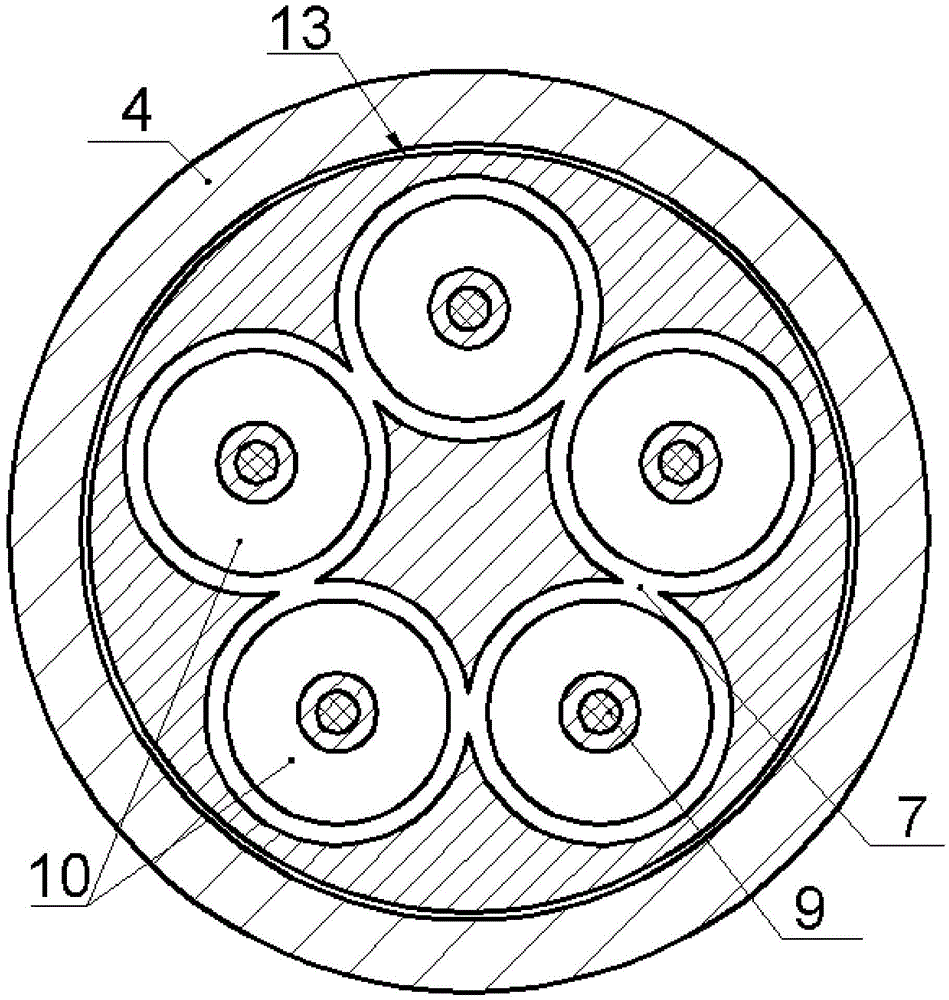
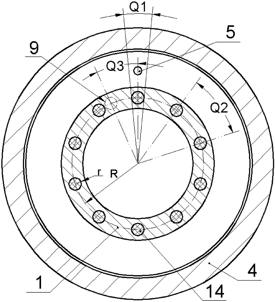
[0018] like Figure 1 ~ Figure 4 As shown, it includes inner ring 1, balls 2, cage 3, and outer ring 4. The width of the outer ring 4 is larger than that of the inner ring 1, and the inner ring 1 is installed in alignment with one side of the outer ring 4. On the non-aligned side, the end surface of the outer ring 4 is fixed with a connecting flange 61 of the cover plate 6 by screws, and the side of the cover plate 6 close to the inner ring 1 is provided with a set of concave cavity 1 62 and a positioning hole 63, and A guard plate 13 is installed by screws, and the guard plate 13 is provided with a cavity two 131 opposite to the cavity one 62 on the cover plate 6 and a positioning shaft opposite to the positioning hole 63 on the cover plate 6 134, at least one through hole 135 for installing the sensor 5, a ring groove 133 for installing the circuit board 15, a boss 136 and a guide hole 132 are provided at the bottom of the second concave cavity 131, and the cover plate 6 In...


PUM


Abstract

The invention relates to a ball bearing with a self-measurement system, and belongs to the technical field of bearings. A cover plate is fixed on the end face of an outer ring; a protection plate is mounted on the cover plate; at least one through hole for mounting of a sensor, a ring slot for mounting of a circuit board, a boss and a guide hole are formed on the protection plate; an annular metal film is pressed between the cover plate and the protection plate; a piezoelectric film is adhered to the side surface of the metal film so as to form a transducer; an excited magnet is arranged on the transducer; the other end of the excited magnet is arranged in the guide hole and can do reciprocating motion along the guide hole; a group of excitation magnets are embedded into the end face of one side, which is close to the protection plate, of an inner ring; the circuit board is fixed in the ring slot through a screw, is connected with the sensor through a lead wire group I and is connected with the transducer through a lead wire group II. The ball bearing with the self-measurement system has the advantages that an automatic power supplying, sensing and monitoring function is realized; the structure of mounting equipment is not required to be changed; true real-time and on-line monitoring is realized; due to the guide hole, twisting and swinging of the excited magnet are prevented, and the transducer is high in reliability.

Description

technical field [0001] The invention belongs to the technical field of bearings, and in particular relates to a ball bearing with a self-measurement system. Background technique [0002] Bearing is a typical mechanical basic part, which has a wide range of applications in the fields of machinery, vehicles, aerospace, ships and energy; however, bearings are also one of the most vulnerable parts in rotating machines, and the failure of rotating machines 30% are caused by bearing failure. Therefore, the state monitoring and early fault diagnosis of bearings have attracted people's attention. On-line monitoring of bearing status has gradually become an indispensable technology in the fields of large wind turbines, ships, high-speed rail, and aircraft. The indicators to be monitored include temperature, vibration, speed, and noise. Early bearing monitoring systems were mainly plug-in. One of the disadvantages was that the distance between the sensor and the signal source was re...

Claims


Application Information

Patent Timeline
Patent Type & Authority Patents(China)
IPC IPC(8): F16C41/00G01M13/04
Inventor 阚君武富佳伟程光明王淑云喻学才傅青青
Owner ZHEJIANG NORMAL UNIVERSITY
Why Eureka
Try Eureka