A temperature self-monitoring ball bearing

A self-monitoring, ball bearing technology, applied in the direction of bearing components, shafts and bearings, bearing assembly, etc., can solve the problem of difficulty in obtaining the running state of the bearing in a timely and accurate manner, and achieve reasonable determination of configuration parameters, strong power generation capability, and novel structure. Effect

Inactive Publication Date: 2017-01-04
ZHEJIANG NORMAL UNIVERSITY
View PDF4 Cites 0 Cited by
  • Summary
  • Abstract
  • Description
  • Claims
  • Application Information

AI Technical Summary

Problems solved by technology

[0003] The present invention provides a temperature self-monitoring ball bearing to solve the problem that the existing bearing monitoring system in actual application is still non-real-time, indirect non-contact measurement, and it is difficult to obtain the running state of the bearing in time and accurately

Method used


Image

  • A temperature self-monitoring ball bearing
  • A temperature self-monitoring ball bearing
  • A temperature self-monitoring ball bearing

Examples


Embodiment Construction

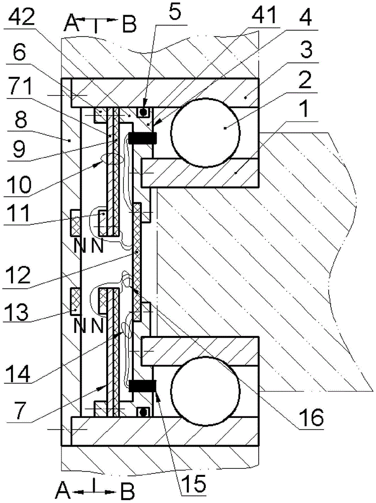
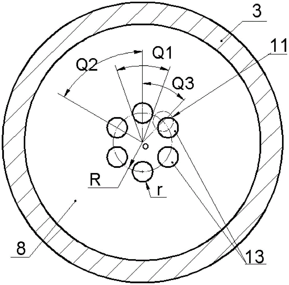
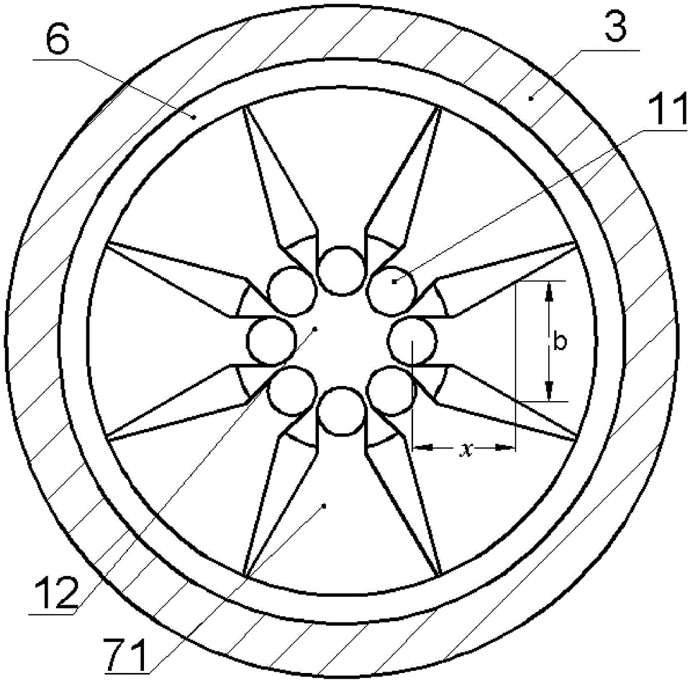
[0014] Such as Figure 1 to Figure 4 As shown, it includes the inner ring 1, the ball 2, the outer ring 3, the width of the outer ring 3 is greater than the width of the inner ring 1, and the inner ring 1 and the side of the outer ring 3 are aligned and installed; On the side, the end face of the inner ring 1 is fixed with a mounting tube 4 by screws, the end face of the outer ring 3 is fixed with an excitation disc 8, the excitation disc 8 is evenly inlaid with excitation magnets 13, and the bottom plate 41 of the installation tube 4 is installed with a circuit board 12 And the sensor 15, the end surface of the side wall 42 of the installation cylinder 4 is crimped with a metal film 7 through the screw and the pressure ring 6, and the O-ring 5 is installed between the outer surface of the side wall 42 of the installation cylinder 4 and the inner surface of the outer ring 3 , the metal film 7 is provided with a cantilever beam 71, the side of the free end of the cantilever bea...


PUM


Abstract

The invention relates to a temperature self-monitoring ball bearing, and belongs to the technical fields of a bearing and monitoring thereof. A mounting barrel is fixed on the end face of an inner ring through a bolt; an exciting plate is fixed on the end face of an outer ring through a bolt; exciting magnets are evenly embedded on the exciting plate; a circuit board and a sensor are arranged on a bottom plate of the mounting barrel; a metal film is pressed on the end face of the lateral wall of the mounting barrel through a bolt and a pressure ring; an O-shaped seal ring is arranged between the outer surface of the lateral wall of the mounting barrel and the inner surface of the outer ring; a cantilever beam is arranged on the metal film; an excited magnet is arranged at one side of the free end of the cantilever beam, near the exciting magnet; a piezoelectric diaphragm is adhered to the other side; an energy harvester is formed after the cantilever beam is adhered to the piezoelectric diaphragm; the energy harvester and the sensor are respectively connected with the circuit board through a lead group 1 and a lead group 2. The temperature self-monitoring ball bearing has the advantages of having a self-energized sensing monitoring function, being used as an independent standard component, having no need on change of the structure of the mounting equipment, and being capable of achieving real-time online monitoring in the real sense.

Description

technical field [0001] The invention belongs to the technical field of bearings and monitoring thereof, and in particular relates to a temperature self-monitoring ball bearing. Background technique [0002] Bearing is a typical mechanical basic part, which is widely used in the fields of machinery, vehicles, aerospace, ships and energy; however, bearing is also one of the most vulnerable parts in rotating machines, and 30% of rotating machinery failures % is caused by bearing failure. Therefore, the state monitoring and early fault diagnosis of bearings have attracted people's attention. On-line monitoring of bearing status has gradually become an indispensable technology in the fields of large wind turbines, ships, high-speed rail, and aircraft. The indicators to be monitored include temperature, vibration, speed, and noise. Early bearing monitoring systems were mainly plug-in. One of the disadvantages was that the distance between the sensor and the signal source was rel...

Claims


Application Information

Patent Timeline
Patent Type & Authority Patents(China)
IPC IPC(8): F16C41/00
Inventor 曾平李胜杰阚君武王淑云程光明
Owner ZHEJIANG NORMAL UNIVERSITY
Why Eureka
Try Eureka