Braking device for vehicle

A brake device and parking brake technology, applied in the direction of brake transmission, brakes, vehicle components, etc., can solve the problems of difficult cover parts, difficult for operators to visually confirm cover parts, floor equipment obstacles, etc., and achieve easy-to-see The effect of visual confirmation

Inactive Publication Date: 2014-10-01
NABLESCO CORP
View PDF6 Cites 2 Cited by
  • Summary
  • Abstract
  • Description
  • Claims
  • Application Information

AI Technical Summary

Problems solved by technology

However, in the structure described in Patent Document 1, the cover portion (31) protrudes only from the cylinder body (13)
Therefore, when the cylinder main body (13) is arranged at a position inward from the side of the railway vehicle, etc., when the operator visually inspects the cover portion (31), the floor equipment becomes an obstacle, and it is difficult for the operator to visually confirm the cover portion ( 31) Location
Therefore, even if the cover part (13) is painted with bright colors, it is difficult to visually confirm the position of the cover part (13), so it is difficult to confirm whether the parking spring brake mechanism is working
In addition, in rainy weather, dusk, etc., it is difficult for light to enter the surroundings of the cover part (13), and it is even more difficult for the operator to visually confirm the position of the cover part (13)

Method used


Image

  • Braking device for vehicle
  • Braking device for vehicle
  • Braking device for vehicle

Examples


no. 1 Embodiment approach

[0055] Braking device

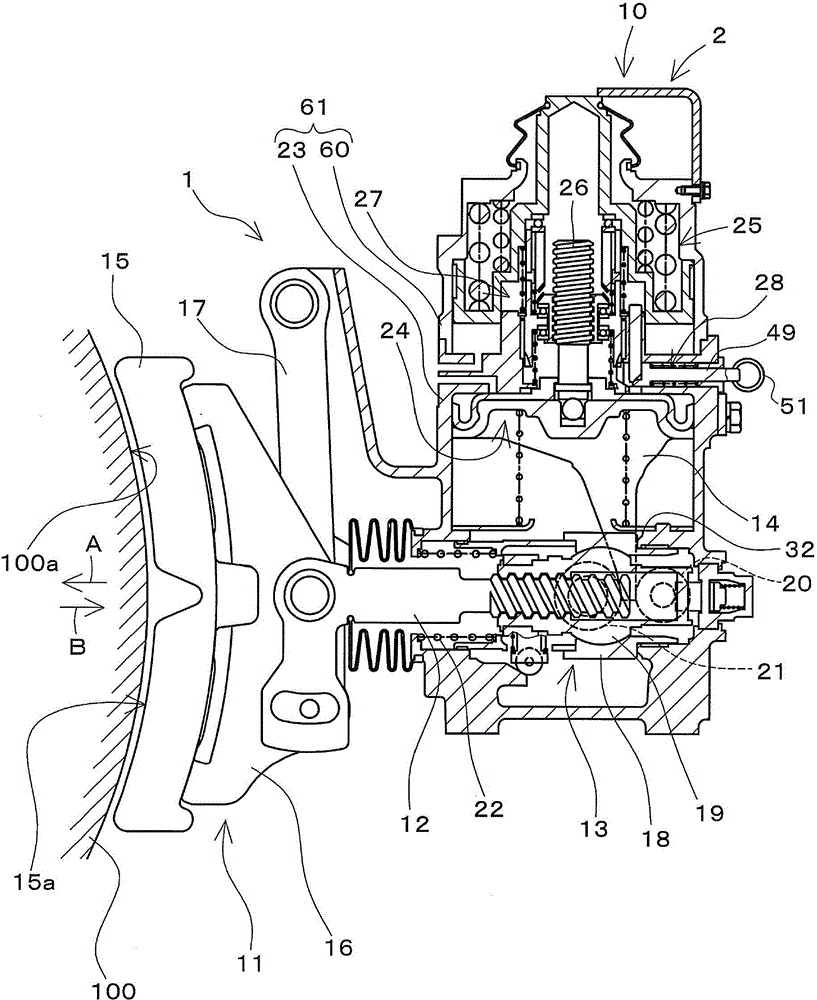
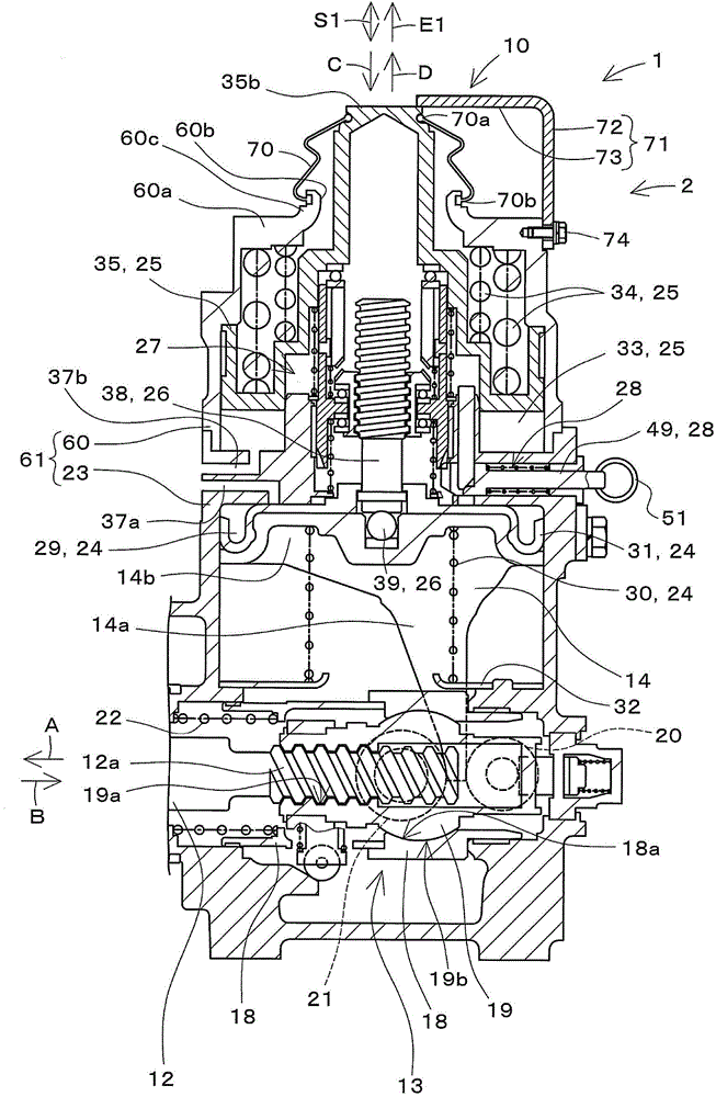
[0056] figure 1 It is a diagram including a partial cross section of the brake device 1 according to the first embodiment of the present invention. figure 2 will be figure 1 The illustrated part of the brake device 1 is an enlarged view showing a brake cylinder device 2 provided in the brake device 1 . figure 1 with figure 2 The illustrated brake device 1 is provided on a railway vehicle (not shown). in addition, figure 1 It is a figure which looked at the brake apparatus 1 from the axle direction of the wheel 100 of a railway vehicle in the state which installed the brake apparatus 1 in a railway vehicle.

[0057] The brake device 1 is configured as a tread brake device. The brake device 1 is configured to include a brake cylinder device 2 , a brake output unit 11 , a rod 12 , a rod support mechanism 13 , a rod drive unit 14 , and the like.

[0058] Furthermore, the brake device 1 is configured to drive the brake output unit 11 supported so ...

no. 2 Embodiment approach

[0169] Next, a second embodiment of the present invention will be described. In addition, in the following, differences from the first embodiment will be mainly described, and the same or similar reference numerals will be assigned to the same structures as those in the first embodiment, and descriptions will be omitted.

[0170] Figure 6 ~ Figure 8 It is a cross-sectional view showing main parts of a brake device 1A according to a second embodiment of the present invention. Image 6 shows the usual braking state, Figure 7 Shows the working state of the parking spring brake, Figure 8 It shows the state where the parking spring brake is temporarily released.

[0171] refer to Image 6 The display device 10A has a measurement member 71A, a first protrusion 75 , and a second protrusion 76 .

[0172] The measurement member 71A has a base 72 and a measurement main body 73A.

[0173] The distal end portion of the measurement main body 73A and the end surface of the one end ...

no. 3 Embodiment approach

[0190] Next, a third embodiment of the present invention will be described. Figure 9 ~ Figure 11 It is a side view showing main parts of a brake device 1B according to a third embodiment of the present invention, and a part is shown in cross section. Figure 9 shows the usual braking state, Figure 10 Shows the working state of the parking spring brake, Figure 11 It shows the state where the parking spring brake is temporarily released.

[0191] refer to Figure 9 , the display device 10B has a first protrusion 75B and a position sensor 77 .

[0192] The first protruding portion 75B is provided to indicate the relative position between the measurement member 71 and the second piston 35 . In addition, the first protruding portion 75B is provided to be in contact with the position sensor 77 .

[0193] The first protruding portion 75B protrudes from the end surface of the one end portion 35 b of the second piston 35 . The first protruding portion 75B is formed in, for exa...


PUM


Abstract

The invention provides a braking device for a vehicle, and the braking device enables the visual affirmation of the working state of a parking braking mechanism to be easier. The braking device (1) is provided with a second piston (35) and a display unit (10). The second piston (35) is a piston for the braking of a parking spring and aims at the braking force generated during the parking of a railway vehicle. The display unit (10) is used for displaying the position of the second piston (35), and comprises a measuring member (71). The measuring member (71) can move relative to the second piston (35) and the top end part (70a) of a dustproof sleeve (70).

Description

technical field [0001] The present invention relates to a vehicle brake device provided on vehicles such as railway vehicles. Background technique [0002] For example, a brake device provided with a parking spring brake mechanism is known as a brake device provided on a railway vehicle (for example, refer to Patent Document 1). The above-mentioned parking spring brake mechanism is used when a railway vehicle is parked. In addition, the parking spring brake mechanism is configured to be actuated by moving the parking piston pressurized by the urging force of the parking spring in a predetermined braking operation direction. [0003] In addition, the brake device disclosed in Patent Document 1 is provided with a structure that allows the operator to visually confirm whether the parking spring brake mechanism is operating. Specifically, the brake device disclosed in Patent Document 1 is provided with a cover portion ( 31 ) for an operator to visually confirm whether the park...

Claims


Application Information

Patent Timeline
Patent Type & Authority Applications(China)
IPC IPC(8): B60T17/22B60T13/38
Inventor 麻野吉雄井原一征
Owner NABLESCO CORP
Why Eureka
Try Eureka