Marker for golf ball

A golf ball and position mark technology, which is applied to golf balls, golf accessories, sports accessories, etc., can solve the problems of troublesome setting operations, inability to maintain an upright state, discomfort, etc., and achieves simple setting operations and easy visual confirmation of the position. target effect

Inactive Publication Date: 2013-02-06
WORK SPIRIT
View PDF7 Cites 0 Cited by
  • Summary
  • Abstract
  • Description
  • Claims
  • Application Information

AI Technical Summary

Problems solved by technology

[0011] The markers described in Patent Document 1 are composed of two mutually independent members such as a first marker with a larger outer diameter and a second marker with a smaller outer diameter. Therefore, if either marker is damaged or lost, the marker The sign can only play the function of the previous sign
In addition, when in use, since the first marker with a larger outer diameter is placed on the putting green, etc., and then the second marker with a smaller outer diameter is sucked and placed, the installation operation is troublesome, and it is easy to misuse the second marker. 2 digit scrolling
[0012] On the other hand, since the erecting portion of the markers described in Patent Document 2 and Patent Document 3 is in the shape of a thin-walled disc, when the erecting portion of the marker is erected during use, when viewed from the plan view direction of the erecting portion, Only a line can be seen during the time, so it is difficult for the players to visually confirm the position of the marker
In addition, if the standing part is frequently rotated and raised, the hinge part will be worn, etc., and the rotation resistance will decrease, making it impossible to maintain the standing state.
Moreover, since the fitting part is formed, when it is inserted into a pocket etc., there is also a problem that the fitting part presses the player's body and feels uncomfortable.

Method used


Image

  • Marker for golf ball
  • Marker for golf ball
  • Marker for golf ball

Examples


Embodiment approach 1

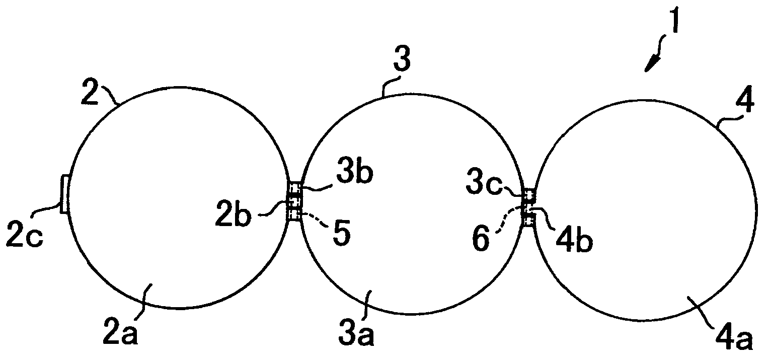
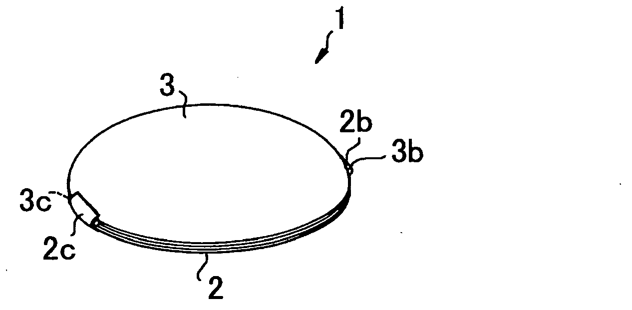
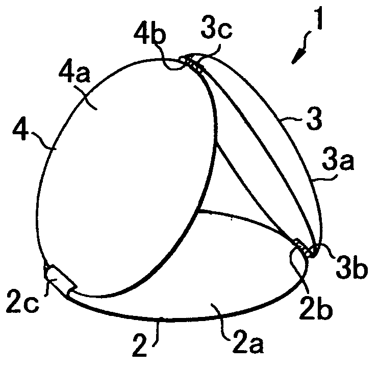
[0040] figure 1 It is a developed view of one embodiment of the golf ball marker of the present invention, figure 2 is the three-dimensional view of its usual appearance, image 3 is a three-dimensional view of its appearance in use, Figure 4 is a side view of it in use.

[0041] Such as Figure 1 to Figure 4 As shown, the golf ball marker 1 of the present invention is composed of a base member 2 , an upper cover member 3 and a standing member 4 .

[0042] The base member 2 has a connecting piece 2b formed at one end of a circular planar plate 2a made of metal material with an outer diameter of 25mm and a thickness of 1mm, and a locking piece 2c formed at the other end of the planar plate 2a. The locking piece portion 2c protrudes upward at a substantially right angle with respect to the planar plate portion 2a.

[0043] The upper cover member 3 is formed with a connecting piece 3b at one end of a circular planar plate portion 3a or curved plate portion made of a metal ...

Embodiment approach 2

[0052] Figure 5 It is a developed view of another embodiment of the golf ball marker of the present invention, Image 6 is a perspective view showing its internal structure, Figure 7 is the three-dimensional view of its usual appearance, Figure 8 is a three-dimensional view of its appearance in use, Figure 9 is its usual bottom view, Figure 10 is its usual top view.

[0053] Such as Figure 5 ~ Figure 8 As shown, the golf ball marker 11 of the present invention is composed of a base member 12 , an upper cover member 13 and a standing member 14 .

[0054] The base member 12 is composed of a circular planar plate portion 12a made of metal material with an outer diameter of 25mm and a wall thickness of 1mm, and a peripheral wall plate portion 12b formed around the planar plate portion 12a. In the connection piece part 12c, the connection piece part 12d is formed in the other end part of the planar plate part 12a. Additionally, if Figure 9 As shown, the central porti...

Embodiment approach 3

[0067] Figure 11 It is a developed view of another embodiment of the golf ball marker of the present invention, Figure 12 is a perspective view showing its internal structure, Figure 13 is the three-dimensional view of its usual appearance, Figure 14 It is a three-dimensional view of its appearance in use.

[0068] Such as Figure 11 to Figure 14 As shown, the golf ball marker 31 of the present invention is composed of a base member 32 , an upper cover member 33 and a standing member 34 .

[0069] The base member 32 is composed of a circular planar plate portion 32a made of metal material with an outer diameter of 25 mm and a wall thickness of 1 mm, and a peripheral wall plate portion 32b formed around the planar plate portion 32a. The connecting piece portion 32c has a locking piece portion 32d formed at the other end portion of the planar plate portion 32a.

[0070] The upper cover member 3 is composed of a circular planar plate portion 33a made of a metal material ...


PUM


Abstract

Provided is a marker for a golf ball, configured by linking a base member, a cap member, and an erecting member. A linking part is formed on one end part of a flat plate part of the base member, and a hook part is formed on the other end part thereof. A first linking part is formed on one end part of a flat plate part of the cap member, and a second linking part is formed on the other end part thereof. A flat plate part of the erecting member has a narrower outer diameter than the flat plate parts of the base member and the cap member, and a linking member is formed on one end part of said flat plate part. By laying the flat plate part of the erecting member flat and covering the flat plate part of the cap member, it is possible to house the erecting member between the base member and the cap member. By erecting the flat plate part of the erecting member and hooking the other end part of the erecting member in the hook part of the flat plate part of the base member, it is possible to erect and support the erecting member.

Description

technical field [0001] The present invention relates to a golf ball marker placed to indicate the position of the golf ball when the golf ball is temporarily picked up on a fairway or a green of a golf course. Background technique [0002] In a golf game, players cannot touch the golf ball with their hands in principle. However, when the ball is hit with sand, mud, etc. attached to it on a fairway, green, etc., the ball may lose control or become unable to spin. Also, when hitting a golf ball on the green, other players' balls may become an obstacle, preventing you from hitting your own ball toward the hole. In this case, in the golf rules, it is stipulated that in order to indicate the position of the ball in a fairway, a putting green, etc., a marker may be placed directly behind the ball facing the hole, and the ball may be temporarily picked up. [0003] Conventionally, coins, plastic thin discs, and the like have generally been used as such markers for golf balls. In...

Claims


Application Information

Patent Timeline
Patent Type & Authority Applications(China)
IPC IPC(8): A63B57/00
CPCA63B57/0075A63B57/353A63B57/35
Inventor 杉本章
Owner WORK SPIRIT
Why Eureka
Try Eureka