Adjustable rifle support

a technology of adjustable support and rifle, which is applied in the direction of gun mounting, ammunition loading, transportation and packaging, etc., can solve the problems of inconvenient and precise vertical adjustment of prior art rifle supports, and achieve the effect of convenient and stable hand-held adjustment, convenient setup and precise vertical adjustmen

Inactive Publication Date: 2005-03-01
LIGI TOOL & ENG
View PDF22 Cites 17 Cited by
  • Summary
  • Abstract
  • Description
  • Claims
  • Application Information

AI Technical Summary

Benefits of technology

It is accordingly an object of the invention to provide a rifle support apparatus with precise vertical adjustment that is conveniently at hand and stable. It is another object that the apparatus be compact for transport and be easily set up. The apparatus of the invention includes a folding stand that lies flat within a recess in a case for transport. The stand has three panels. A first panel is hingedly attached at a first end to the case, and hingedly attached to a first end of a second panel at a second end. The second panel is hingedly attached at its second end to a third panel. The third panel is slidably mounted within the case recess for translatory motion toward and away from the first end of the first panel. When the third panel slides toward the first end of the first panel, the joint between the first and second panels rises vertically from the recess in the case. A rifle rest for the forward end of the rifle is mounted at that joint. The precise control of the translatory motion of the third panel is provided by a rack and pinion mechanism through a worm gear controlled by a hand wheel. By operating the vertical adjustment through a worm gear, the sliding position is stable without need to lock the position. For coarse adjustment of the translatory motion of the third panel, the rack and pinion mechanism is readily disengaged. This facilitates set-up and lowering of the rifle rest to lie flat within the case recess after use. A height-adjustable rest for the rifle stock is provided for use with the rifle rest. It may be storable within the case for transport and storage. These and other objects, features, and advantages of the invention will become more apparent when the detailed description is studied in conjunction with the drawings in which like elements are designated by like reference characters in the various drawing figures.

Problems solved by technology

Prior art rifle supports have not provided precise and stable vertical adjustment.

Method used


Image

  • Adjustable rifle support
  • Adjustable rifle support
  • Adjustable rifle support

Examples


Embodiment Construction

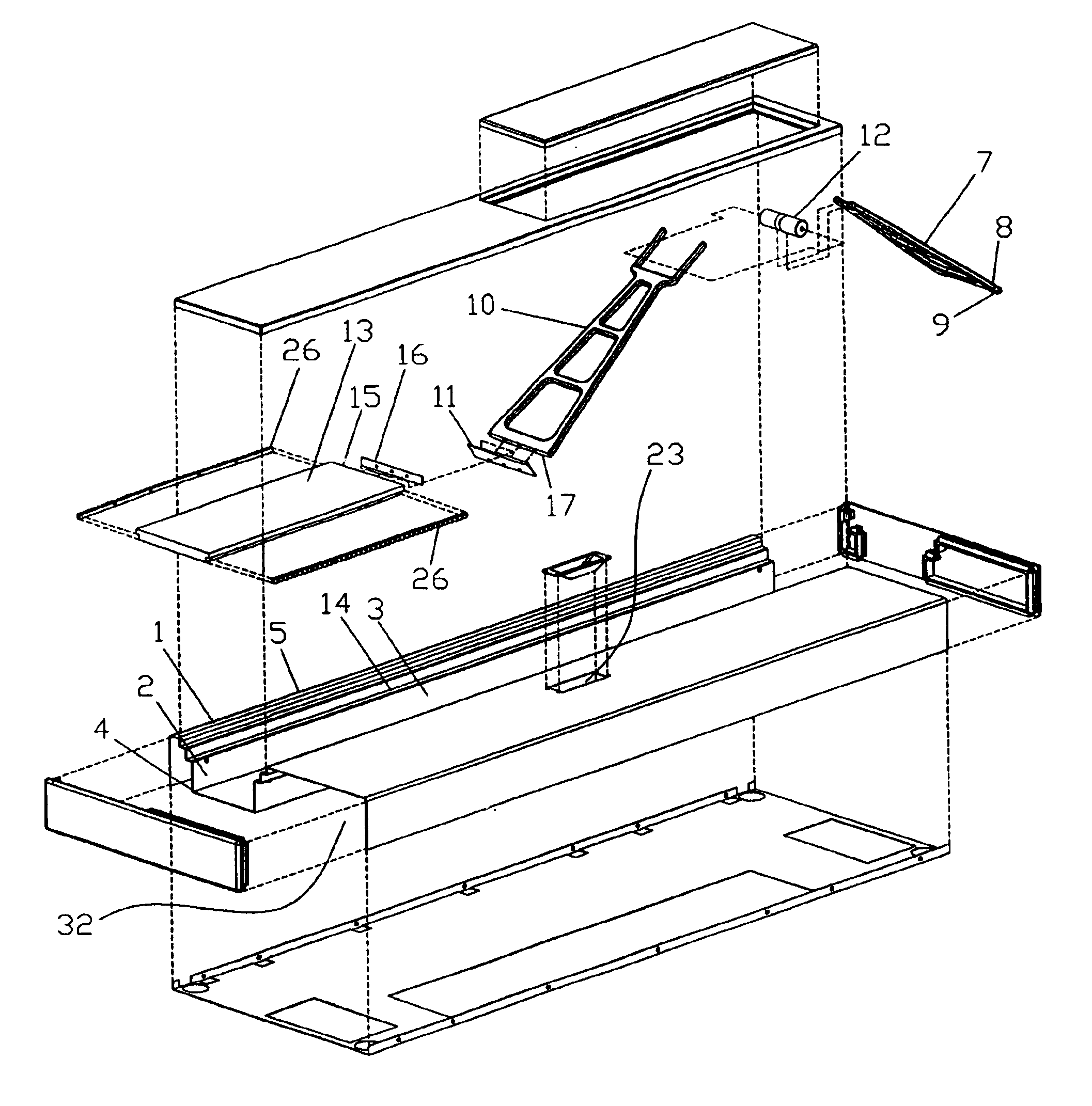
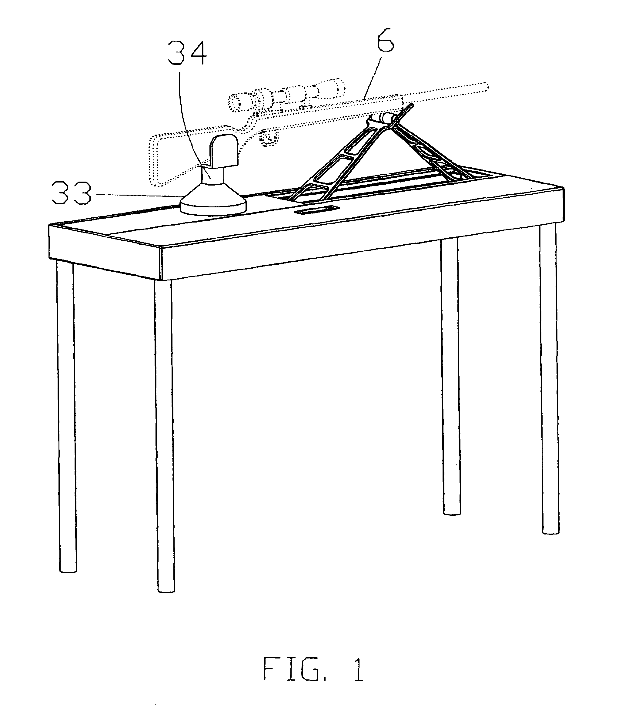
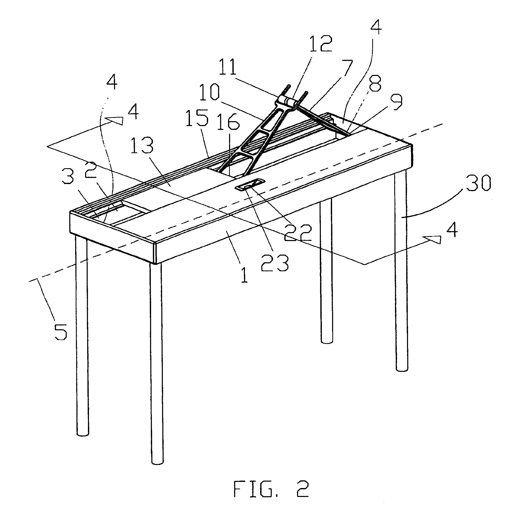
Referring now to the drawing FIGS. 1-7, the adjustable support of the invention includes a case 1 with a long axis 5 supported on legs 30 that fit into sockets 31. The legs may be removed and fit into leg storage recess 32 in the underside of the case for transport and storage. A rectangular recess 22 in the upper surface of the case has long sides 3 and short sides 4. A first panel 7 has a first end 8 hingedly attached to a short end of the recess. A second panel 10 has a first end with a hinge 11 connected to a second end of panel 7. A third panel 13 lies flat and slides in slide mount 14 in the recess. It has a first end 15 hingedly connected at hinge 16 to the second end 17 of the second panel 10. A pair of elongate racks 21 are inset in the long sides of the third panel 13. A motion control means 18 includes a pinion gear 20 that engages one of the racks to provide precise rectilinear movement of the panel 13. As it advances toward the first panel, it forces panels 7 and 10 to ...


PUM


Abstract

A portable support apparatus provides for fine vertical adjustment of a support element for the forward portion of a rifle with a motion control including a worm gear and a rack and pinion. Whatever elevation is selected by rotation of the control will be maintained without need to lock the position. A manual or electrical actuator may be provided. A height adjustable rest for the stock end of the rifle also be provided. The apparatus includes legs that may be removed and stored within the case containing the apparatus.

Description

This invention relates to firearms accessories, and more particularly to a rifle support with fine vertical adjustment.BACKGROUND OF THE INVENTIONWhen target shooting and hunting the accuracy of the rifle sights is critical. When adjusting and using the sights, the position in which the rifle is held when firing with the sights is also critical. Prior art rifle supports have not provided precise and stable vertical adjustment.SUMMARY OF THE INVENTIONIt is accordingly an object of the invention to provide a rifle support apparatus with precise vertical adjustment that is conveniently at hand and stable. It is another object that the apparatus be compact for transport and be easily set up. The apparatus of the invention includes a folding stand that lies flat within a recess in a case for transport. The stand has three panels. A first panel is hingedly attached at a first end to the case, and hingedly attached to a first end of a second panel at a second end. The second panel is hinge...

Claims


Application Information

Patent Timeline
Patent Type & Authority Patents(United States)
IPC IPC(8): F41A23/00F41A27/24F41A23/60F41A27/00F41A23/16
CPCF41A23/16F41A27/24F41A23/60
Inventor WALRATH, ALDEN B.
Owner LIGI TOOL & ENG
Why Eureka
Try Eureka