Retina optical coherence chromatography detection-display system

An optical coherence tomography and display system technology, applied in the field of retinal optical coherence tomography detection-display system, can solve the problems of large system and single function, etc.

Active Publication Date: 2014-10-29
BEIJING INSTITUTE OF TECHNOLOGYGY
View PDF7 Cites 17 Cited by
  • Summary
  • Abstract
  • Description
  • Claims
  • Application Information

AI Technical Summary

Problems solved by technology

[0004] The technical problem to be solved by the present invention is how to solve the problem that the existing retinal optical coherence tomography detection system has a single function and a huge system

Method used


Image

  • Retina optical coherence chromatography detection-display system
  • Retina optical coherence chromatography detection-display system
  • Retina optical coherence chromatography detection-display system

Examples


Embodiment 1

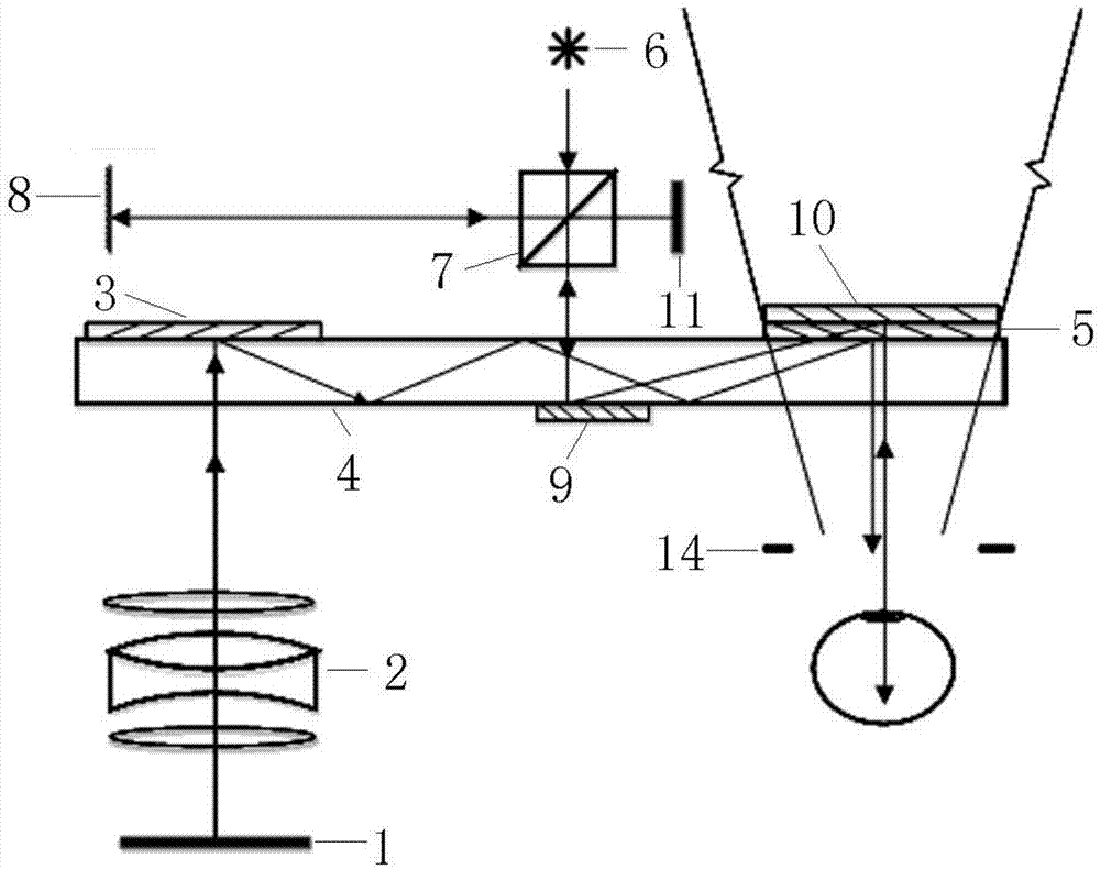
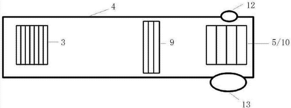
[0085] Example 1, figure 2 A top view of a retinal optical coherence tomography detection-display system provided in this embodiment, image 3 A front view of a retinal optical coherence tomography detection-display system provided in this embodiment, Figure 4 A side view of a retinal optical coherence tomography detection-display system provided in this embodiment;

[0086] Wherein the first input diffractive optical element 3 is located on the rear side of the input end of the optical waveguide 4, the first output diffractive optical element 5 is located on the rear side of the output end of the optical waveguide 4, the second input diffractive optical element 9 is located on the front side of the optical waveguide 4, and the second The output diffractive optical element 10 is located on the rear side of the output end of the optical waveguide 4, and is located on the first output diffractive optical element 5; of course, the relative position between the second output di...

Embodiment 2

[0095] Example 2, such as Figure 6 As shown, the first input diffractive optical element 3 is a transmissive diffractive optical element and is located on the front side of the input end of the optical waveguide 4. The arrangement and type of other diffractive optical elements are the same as those in Embodiment 1, so the transmission principle is also the same.

Embodiment 3

[0096] Example 3, such as Figure 7 As shown, the second output diffractive optical element 10 is a transmissive diffractive optical element located on the front side of the output end of the optical waveguide 4. The arrangement and type of other diffractive optical elements are the same as those in Embodiment 1, so the transmission principle is also the same.


PUM


Abstract

The invention relates to a retina optical coherence chromatography detection-display system. The retina optical coherence chromatography detection-display system comprises a first light path channel for displaying image information, a second light path channel for tracking retina information, a third light path channel formed by an external natural light channel and a fourth light path channel for detecting pupils. In combination with the optical waveguide display technology and the Michelson interference technology, the retina optical coherence chromatography detection-display system overcomes the defects of an original retina optical coherence chromatography detection system, can detect the structure of the retina, can be used for studying the relations between pupil movement, dilation and miosis and structural features of the retina by changing displayed images, also has fluoroscopy and display functions and can be applied to medical research, pathologic analysis, lie detection and other aspects.

Description

technical field [0001] The invention relates to retinal optical coherence tomography technology, in particular to a retinal optical coherence tomography detection-display system. Background technique [0002] Retinal coherence tomography technology uses infrared weak coherent light to irradiate the retinal tissue to be tested, and generates interference according to the coherence of the light. After analyzing and processing the coherent signal, the retinal tissue surface image is formed. It has non-radiation, non-invasive, and high axial resolution. , The advantages of real-time imaging. Retinal optical coherence tomography is an optical instrument that uses this technology to analyze retinal structures and detect retinal lesions. The retinal optical coherence tomography detection system and the signal acquisition and processing system are important components of the retinal optical coherence tomography. Its basic principle is as figure 1 As shown, the infrared laser sour...

Claims


Application Information

Patent Timeline
Patent Type & Authority Applications(China)
IPC IPC(8): A61B3/14A61B3/12
Inventor 刘娟韩剑姚新程王涌天
Owner BEIJING INSTITUTE OF TECHNOLOGYGY
Why Eureka
Try Eureka