Centrifugal type impeller and blowing and sucking device comprising centrifugal type impeller

A centrifugal, impeller technology, applied in the components of pumping devices for elastic fluids, non-variable-capacity pumps, machines/engines, etc., can solve the problems of low output wind pressure and low efficiency

Inactive Publication Date: 2014-12-31
POSITEC POWER TOOLS (SUZHOU) CO LTD
View PDF6 Cites 11 Cited by
  • Summary
  • Abstract
  • Description
  • Claims
  • Application Information

AI Technical Summary

Problems solved by technology

[0005] The forward impeller can output high air pressure, but the efficiency is low; while the backward impeller has high efficiency, but the output air pressure is low, both have advantages and disadvantages

Method used


Image

  • Centrifugal type impeller and blowing and sucking device comprising centrifugal type impeller
  • Centrifugal type impeller and blowing and sucking device comprising centrifugal type impeller
  • Centrifugal type impeller and blowing and sucking device comprising centrifugal type impeller

Examples


Embodiment Construction

[0028] The disclosure of the present invention discloses a blowing device. In this embodiment, the blowing device is an AC blowing machine. Of course, the blowing device can also be a blower, and the power source of the blowing device can also be a gasoline engine or a DC battery. Bag.

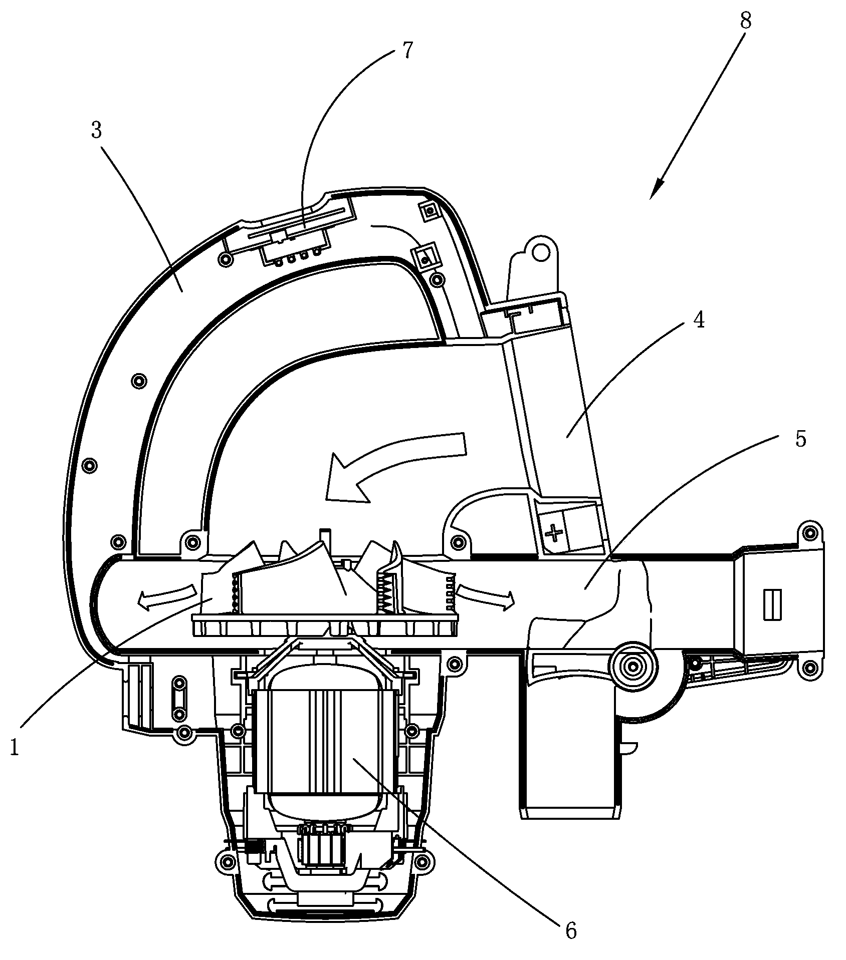
[0029] see figure 1 As shown, the air blower includes a main body housing 8 provided with an operating handle 3 . The main body housing 8 is provided with an air inlet 4 and an air outlet 5 . The main body housing 8 is provided with a motor 6 and a fan 1 . The operating handle 3 is provided with a switch 7 for controlling the opening and closing of the motor 6 . After the switch 7 is activated, the fan 1 rotates at a high speed under the drive of the motor 6 and generates negative pressure, so that the airflow enters from the air inlet 4 and flows out from the air outlet 5 rapidly. The air inlet 4 and the air outlet 5 can be connected to the corresponding blowing and absorbing parts respecti...


PUM


Abstract

The invention relates to a centrifugal type impeller which comprises a wheel disk, a wheel hub and a plurality of blades, wherein the wheel hub is positioned at the center of one side surface of the wheel disk and is provided with a center axial line; an impeller rotates around the center axial line; the multiple blades are arranged on the side surface and are positioned in an annular region surrounded by the periphery of the wheel hub and the periphery of the wheel disk; the cross sections of the blades are S-shaped along the direction perpendicular to the center axial line and comprise two tangent curves with opposite directions; the two curves comprise front blade sections extending from the end part of the wheel hub to a tangent point and rear blade sections extending from the tangent point to the periphery of the wheel disk; the tangent point is positioned at the position which is 76-95 percent of the chord length of each blade away from the end part of the wheel hub. The blades are S-shaped, and the tangent point of the S-shaped curves is positioned at the position which is 76-95 percent of the chord length of each blade; the position of the tangent point enables the rolling suction range of vortex to be effectively suppressed and the intensity of the vortex to be reduced after vortex formation and before vortex falling, and therefore, the flowing resistance of air flow is reduced, and the air discharging efficiency of the impeller is improved. The invention also relates to a blowing and sucking device comprising the centrifugal type impeller.

Description

technical field [0001] The invention relates to a centrifugal impeller. [0002] The invention also relates to a blowing device comprising the centrifugal impeller. Background technique [0003] Existing blowing and sucking devices (comprising blower and blowing and sucking machine) mainly include air inlet, air outlet, volute, the impeller that is located in the volute, the motor that is used to drive impeller to rotate, and blowing and adsorbing parts. Generally speaking, the impellers in the blowing device are all centrifugal impellers. The centrifugal impeller mainly includes a disc and multiple blades arranged around the disc. Among them, the shape and arrangement of the blades determine the centrifugal impeller to a certain extent. The air volume, air output efficiency and noise quality of the impeller. [0004] According to the installation angle of the blade outlet, the centrifugal impeller can be divided into a forward impeller and a backward impeller. The instal...

Claims


Application Information

Patent Timeline
Patent Type & Authority Applications(China)
IPC IPC(8): F04D29/28F04D29/30
CPCF04D29/281F04D29/30F05D2250/70
Inventor 刘金花
Owner POSITEC POWER TOOLS (SUZHOU) CO LTD
Why Eureka
Try Eureka