A sheet slitting machine

A slitting machine and sheet material technology, applied in the attachment of shearing machines, knives for shearing machine devices, shearing devices, etc., can solve the problem of difficulty in forming straight edges, affecting production efficiency, bending, etc. problem, to achieve the effect of smooth cutting process, simple structure and preventing wrinkling

Active Publication Date: 2017-02-08
韶关市高信塑胶制品有限公司
View PDF1 Cites 1 Cited by
  • Summary
  • Abstract
  • Description
  • Claims
  • Application Information

AI Technical Summary

Problems solved by technology

However, it also has the following disadvantages: 1. Since the slitting tool is designed in the way of setting up and down the knife, the blade of the knife is relatively thin, which is easy to cause wear and tear during the cutting of the sheet. According to statistics, the new knife cuts the film material , Generally, only about 50 tons can be cut and the knife needs to be changed or sharpened. Generally, it takes half a day for workers to sharpen the knife, which seriously affects the production efficiency; Forms a straight edge, will produce a curved deformation
3. The tool for cutting thin film materials is easy to wear, so it is also difficult to cut metal sheets, and the application range is narrow
At present, the above-mentioned problems are still not resolved

Method used


Image

  • A sheet slitting machine
  • A sheet slitting machine
  • A sheet slitting machine

Examples


Embodiment Construction

[0024] The technical solution of the present invention will be further described in detail below in conjunction with specific embodiments.

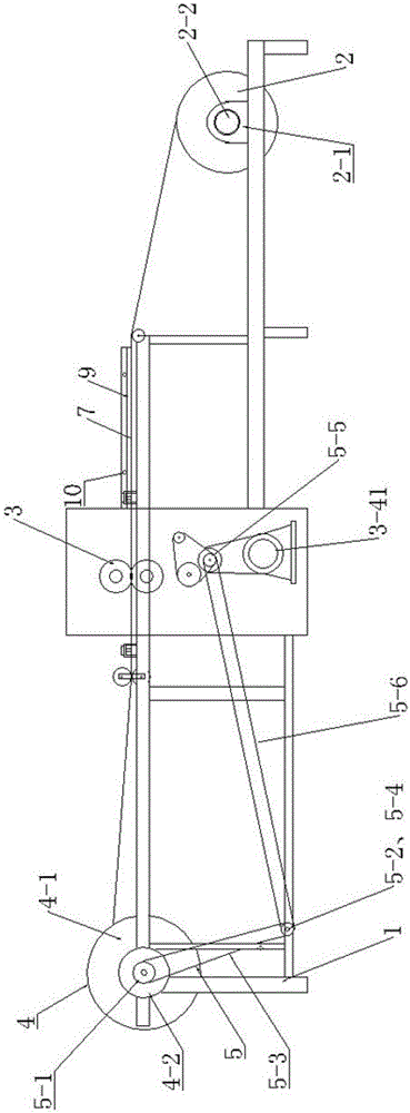
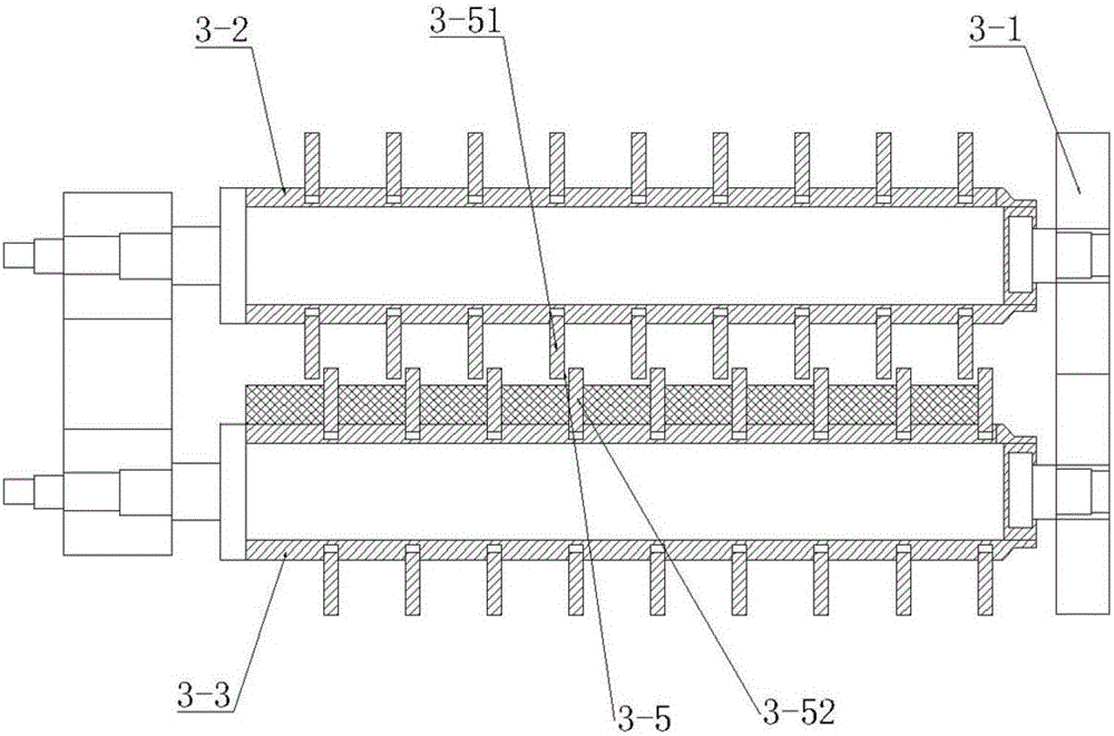
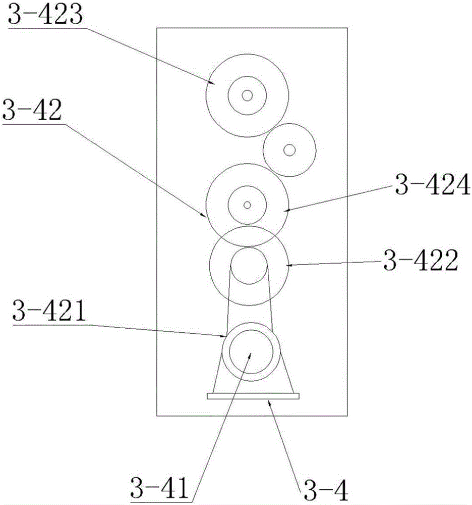
[0025] Such as Figure 1-Figure 8 As shown, a sheet slitting machine of the present invention comprises a frame 1 and a strip feeding mechanism 2, a slitting device 3, a strip winding mechanism 4, a strip loading mechanism 2, a strip The rewinding mechanism 4 is located at the front and rear of the slitting device 3, and the slitting device 3 includes a knife shaft support 3-1, upper and lower knife shafts 3-2, 3-3, and a knife shaft that drives the upper and lower knife shafts to rotate Several groups of shearing modules 3-5 arranged at certain intervals between the power unit 3-4 and the upper and lower cutter shafts, each group of shearing modules consists of an upper cutter 3-51 on the upper cutter shaft and a lower cutter shaft The upper and lower cutters 3-52 are formed, the upper cutter 3-51 and the lower cutter 3-52 are arranged ...


PUM


Abstract

The invention discloses a sheet stock slitting machine. The sheet stock slitting machine comprises a rack as well as a strip feeding mechanism, a slitting device and a strip rolling mechanism which are arranged on the rack, wherein the strip feeding mechanism and the strip rolling mechanism are respectively arranged in the front of and behind the slitting device. The sheet stock slitting machine is characterized in that the slitting device comprises a cutter shaft bracket, an upper cutter shaft, a lower cutter shaft and a cutter shaft power device for driving the upper cutter shaft and the lower cutter shaft to rotate; a plurality of groups of shearing modules are arranged at certain intervals between the upper cutter shaft and the lower cutter shaft; each group of shearing module is composed of an upper cutter on the upper cutter shaft and a lower cutter on the lower cutter shaft, and the upper cutters and the lower cutters are staggered at a horizontal interval of 0-2mm, and the distance between the upper cutter shaft and the lower cutter shaft is less than the radius sum of the upper cutters and the lower cutters. The sheet stock slitting machine is capable of slitting materials such as sheet metal strips and plastic films and is simple in structure, stable in operation and high in precision, the cutters are durable, and products are good in quality and free of deckle edges.

Description

technical field [0001] The invention relates to the technical field of slitting equipment, and more specifically relates to a slitting equipment that can be used for processing various sheet materials such as film, plastic, aluminum sheet, and copper sheet. Background technique [0002] The slitting machine is a kind of equipment for longitudinal cutting of wide roll materials, which is to slit the strip into several strips of required specifications. Classified from the scope of use, including: 1. Used for slitting paper types, which is also the mainstream product in packaging equipment at present, and is often seen in the packaging market; 2. Used for slitting leather, cloth, plastic, film, etc. 3. Used for slitting metal coils, such as slitting strip steel, stainless steel, copper... It is mainly used for steel processing plants, fixed steel market operators, rolling mills, electrical industry, automobiles, stamping parts, etc. Among the above three slitting machines, th...

Claims


Application Information

Patent Timeline
Patent Type & Authority Patents(China)
IPC IPC(8): B26D1/24B26D7/26B26D5/08B26D7/32B23D19/06B23D33/00B23D35/00
Inventor 麦鹤远
Owner 韶关市高信塑胶制品有限公司
Why Eureka
Try Eureka