Refrigeration device

A refrigeration device and refrigerant technology, applied in the direction of refrigerants, refrigerators, refrigeration components, etc., can solve the problem of increasing the discharge temperature of the compressor, and achieve the effect of suppressing the increase in size and ensuring the function of reducing the discharge temperature.

Active Publication Date: 2015-02-04
DAIKIN IND LTD
View PDF6 Cites 5 Cited by
  • Summary
  • Abstract
  • Description
  • Claims
  • Application Information

AI Technical Summary

Problems solved by technology

In the case of using R32 as the refrigerant, the discharge temperature of the compressor tends to increase compared to the case of using R410A and R22 as the refrigerant

Method used


Image

  • Refrigeration device
  • Refrigeration device
  • Refrigeration device

Examples


no. 1 approach >

[0044] (1) The overall structure of the air conditioner

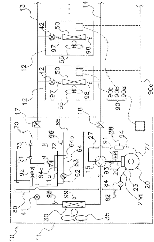
[0045] figure 1 It is a diagram showing a refrigerant piping system of an air conditioner 10 which is a refrigeration device according to an embodiment of the present invention. The air conditioner 10 is a refrigerant piping system split-type air conditioner, and performs cooling and heating of each room in a building by performing a vapor compression refrigeration cycle operation. The air conditioner 10 includes: an outdoor unit 11 as a heat source unit; a plurality of indoor units 12 as utilization units; and a liquid refrigerant communication pipe 13 and a gas refrigerant communication pipe connecting the outdoor unit 11 and the indoor unit 12 as a refrigerant communication pipe. Connecting pipe 14. which is, figure 1 The refrigerant circuit of the shown air conditioner 10 is constituted by connecting an outdoor unit 11 , an indoor unit 12 , and refrigerant communication pipes 13 and 14 . When the refrigerant com...

no. 2 approach >

[0115] (1) Structure of the air conditioner

[0116] In the air conditioner of the second embodiment, the outdoor unit 11 of the air conditioner 10 of the first embodiment using R32 as the refrigerant is replaced with Figure 5 Outdoor unit 211 is shown. In the air conditioner of the second embodiment, the outdoor unit 211 is arranged at a position lower than the indoor unit 12, and the height position of the outdoor unit 211 is greatly different from the height position of the highest indoor unit among the indoor units 12. The height difference becomes larger. Hereinafter, the outdoor unit 211 will be described by assigning the same reference numerals to some parts that overlap with the outdoor unit 11 of the first embodiment and omitting description.

[0117] The outdoor unit 211 mainly includes a compressor 20, a four-way switching valve 15, an outdoor heat exchanger 30, an outdoor expansion valve 41, a bridge circuit 70, a high-pressure storage tank 280, an electric valv...


PUM


Abstract

A refrigeration device is configured in such a manner that an increase in the size of a heat exchanger for injection is minimized and in such a manner that the function of reducing the discharge temperature of a compressor is ensured. An air conditioning device (10) using an R32 refrigerant is provided with: a compressor (20); an indoor heat exchanger (50); an outdoor expansion valve (41); an outdoor heat exchanger (30); a branch pipe (62); an electric valve (63) and a heat exchanger (64), which are used for injection; a high-pressure receiver (80); and the like. The heat exchanger (64) allows the exchange of heat between a refrigerant which flows though a main refrigerant flow passage (11a) and a refrigerant which has passed through the electric valve (63) in the branch pipe (62). A first injection flow passage (65) conducts a refrigerant to the compressor (20), the refrigerant having flowed through the branch pipe (62) and exited from the heat exchanger (64). A second injection flow passage (82) conducts a refrigerant gas component in the high-pressure receiver (80) to the compressor (20).

Description

technical field [0001] The present invention relates to a refrigeration device, in particular to a refrigeration device using R32 as a refrigerant. Background technique [0002] Conventionally, as a refrigeration device such as an air conditioner, there is a device using R32 as a refrigerant. In the case of using R32 as the refrigerant, the discharge temperature of the compressor tends to increase compared to the case of using R410A or R22 as the refrigerant. In recognition of this problem, an air conditioner that achieves a decrease in refrigerant discharge temperature while using R32 is described in Patent Document 1 (Japanese Patent Laid-Open No. 2009-127902 ). In this air conditioner, a part of liquid refrigerant flowing out of a gas-liquid separator arranged in a high-pressure line is bypassed to a compressor, and the bypass refrigerant is changed into a flash gas state by an internal heat exchanger. In addition, by injecting the bypass refrigerant that becomes the fl...

Claims


Application Information

Patent Timeline
Patent Type & Authority Applications(China)
IPC IPC(8): F25B1/00F25B13/00F25B41/20
CPCF25B13/00F25B2400/13F25B2313/005F25B2313/0272F25B1/10F25B2313/0233F25B2313/006F25B9/002F25B2313/02741F25B1/00F25B41/00F25B1/005F25B49/02F25B2500/17F25B2600/05F25B2345/004F25B41/20F25B41/24F25B2500/12F25B2600/2509F25B2700/1931F25B2700/195F25B2600/2515
Inventor 河野聪松冈慎也冈昌弘
Owner DAIKIN IND LTD
Why Eureka
Try Eureka