Cutter swept volume modeling method

A modeling method and scanning volume technology, applied in the field of numerical control, can solve the problems of time-consuming calculation process and high time complexity of tool scanning volume

CN104345687AActive Publication Date: 2015-02-11中国科学院沈阳计算技术研究所有限公司
4 Cites 10 Cited by

Patent Information

Authority / Receiving Office
CN · China
Patent Type
Applications(China)
Current Assignee / Owner
Publication Date
2015-02-11

Smart Images

  • Figure 1
    Figure 1
  • Figure 2
    Figure 2
  • Figure 3
    Figure 3
Patent Text Reader

Abstract

The invention relates to a cutter swept volume modeling method, in particular to a method for expressing a universal cutter model in a cutter frame system by implicit functions in the numerical control machining simulation application and expressing a universal cutter model swept volume by four-dimensional implicit functions comprising time parameters by a rigid motion frame theory and counter movement means. In the machining simulation, the position relationship between a point and the swept volume is rapidly judged so as to realize efficient material removing simulation and collision and interference detection.
Need to check novelty before this filing date? Find Prior Art

Description

technical field

[0001] The invention relates to numerical control technology, in particular to a tool scanning volume modeling method. Background technique

[0002] For the CNC machining program used for the first time, its correctness and safety cannot be guaranteed, and it must be verified. Compared with the online debugging method of machine tools, CNC machining simulation has the characteristics of high efficiency and low cost. The modeling method of tool swept volume is one of the key technologies of NC machining simulation, which greatly affects the efficiency of NC machining simulation. The traditional explicit parameter method has the following problems in constructing the swept volume of the tool: First, for the tool model with complex contours, the surface of the swept volume needs to be constructed by calculating the critical line under the condition that the normal vector of the tool surface is orthogonal to the moving direction at each moment. , the calculatio...

Examples

Embodiment Construction

[0055] The present invention will be described in detail below with reference to the accompanying drawings.

[0056] The present invention includes the following steps (such as Figure 5 shown):

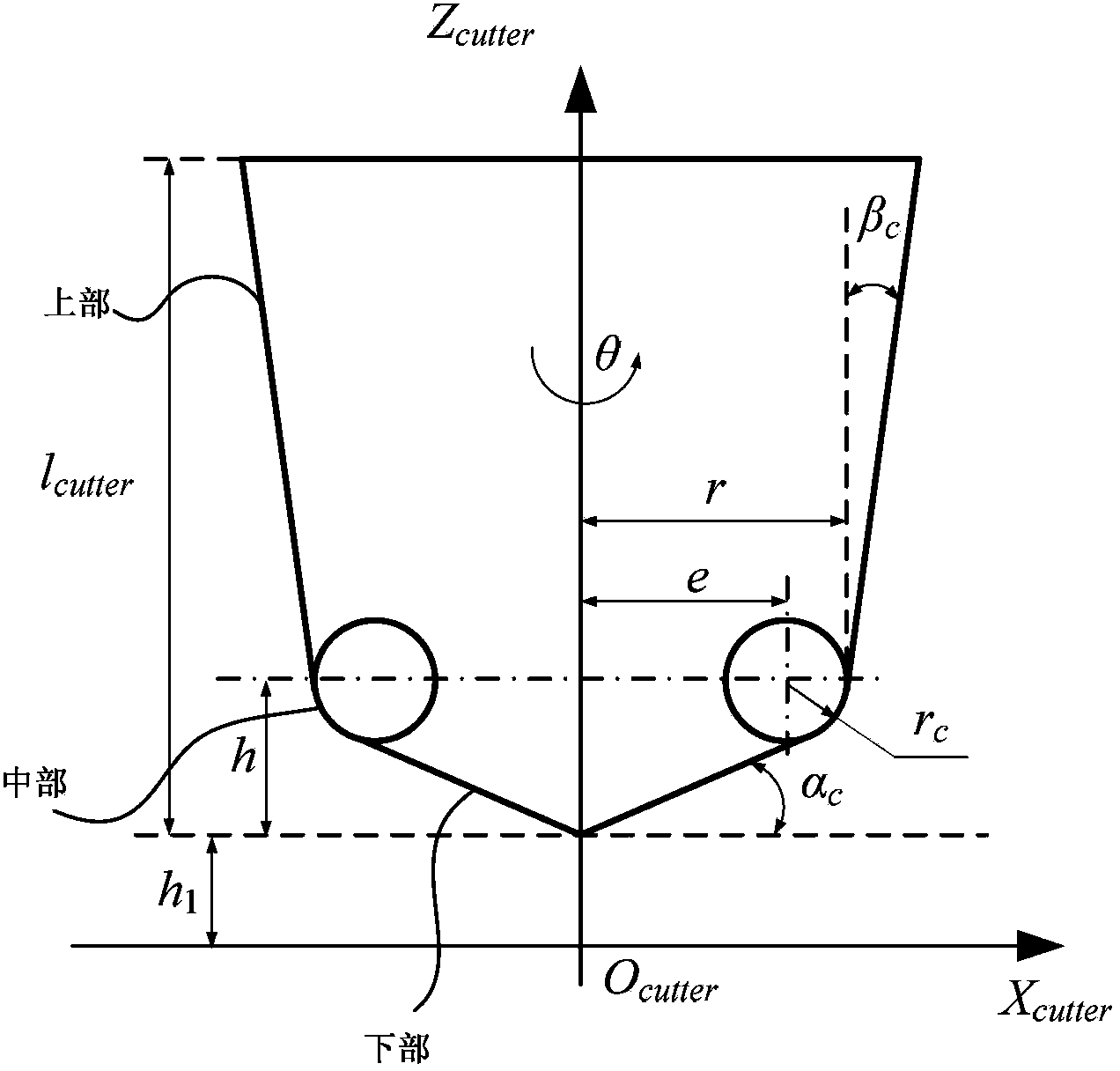
[0057] According to the general tool model (such as figure 1 shown) to calculate the implicit function expression T(x,y,z)=0 of the tool in the tool frame system;

[0058] The implicit function expression of the general tool model in the tool frame system is specifically:

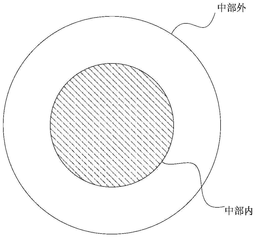
[0059] The implicit function expression of the general tool model is divided into three parts, namely the upper part, the middle part and the lower part (such as figure 1 shown). The middle part is divided into the middle part outside and the middle part inside (such as figure 2 shown).

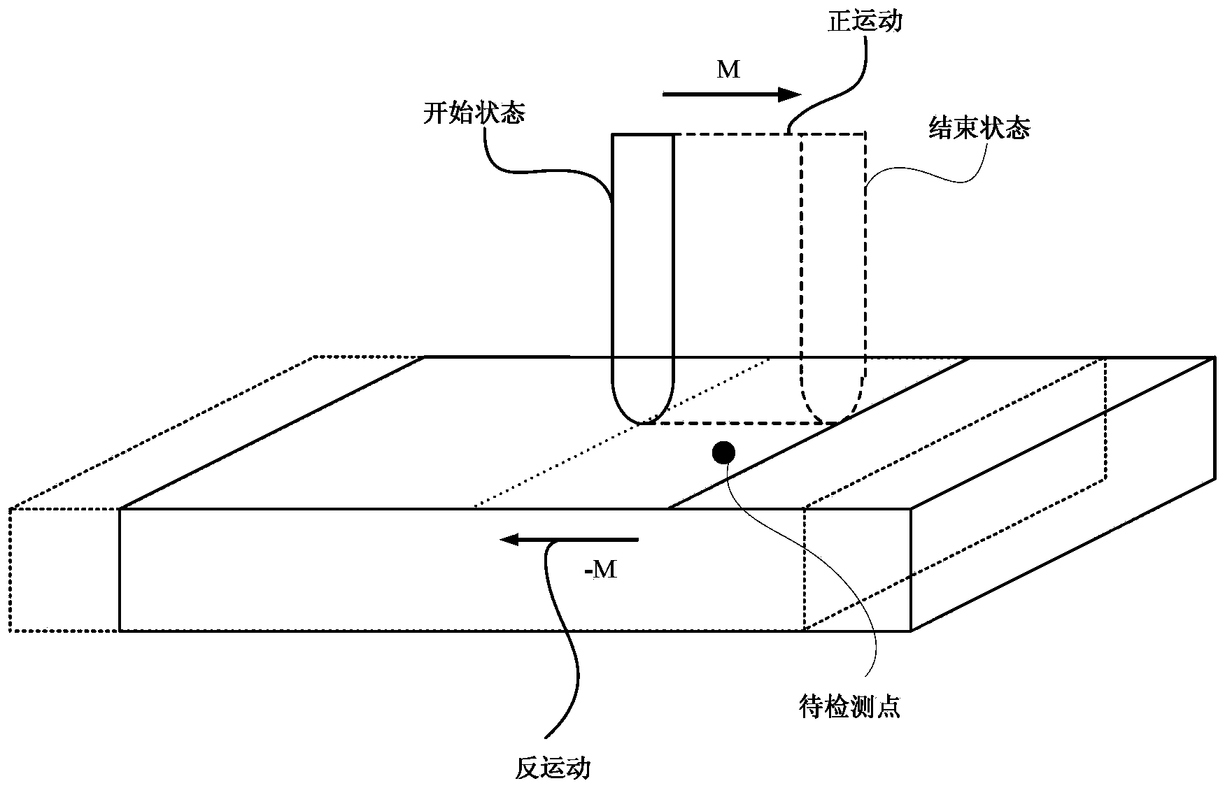
[0060] According to the frame theory of rigid body motion and the inverse motion relationship between the tool and the workpiece. Calculate the conversion relationship between the tool frame system and the workpiece frame...