Eureka AIR delivers breakthrough ideas for toughest innovation challenges, trusted by R&D personnel around the world.

Switching power supply and surge protection circuit and method adaptive to same

A switching power supply and surge protection technology, applied in the electronic field, can solve the problems of large switching power supply, complex circuit structure, high circuit cost, etc., and achieve the effect of improving efficiency, high efficiency and effective protection

Inactive Publication Date: 2015-02-18
SILERGY SEMICON TECH (HANGZHOU) CO LTD
View PDF4 Cites 11 Cited by
  • Summary
  • Abstract
  • Description
  • Claims
  • Application Information

AI Technical Summary

Problems solved by technology

[0012] Using the above-mentioned RCD circuit to absorb the surge energy requires the introduction of a large number of devices into the Buck switching power supply, making the structure of the circuit complex and difficult to integrate, resulting in an excessively large switching power supply
In addition, the ability of capacitor C5 to absorb surge energy is related to the capacitance of capacitor C5 itself. The larger its capacitance, the stronger its ability to absorb surge energy. However, the use of a capacitor with a large capacitance will further increase the volume of the switching power supply. Too large, and the circuit cost is also high

Method used


Image

  • Switching power supply and surge protection circuit and method adaptive to same
  • Switching power supply and surge protection circuit and method adaptive to same
  • Switching power supply and surge protection circuit and method adaptive to same

Examples


Embodiment 1

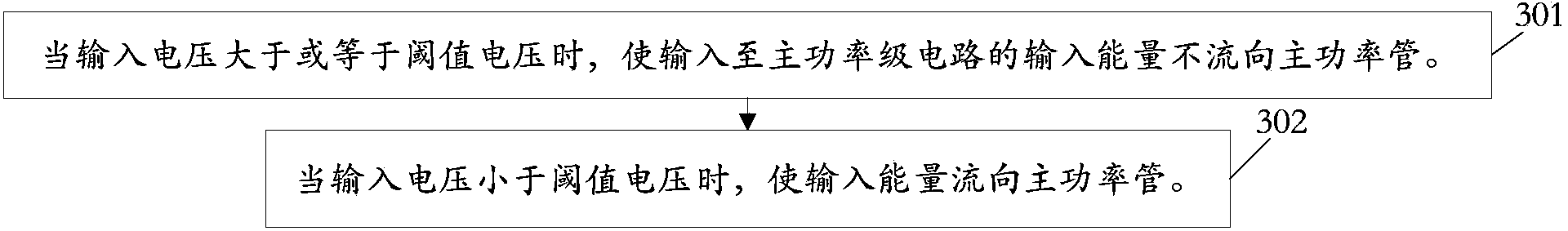
[0057] image 3 This embodiment provides a schematic flow diagram of a surge protection method suitable for switching power supplies, see image 3 As shown, the method mainly includes:

[0058] Step 301: When the input voltage is greater than or equal to the threshold voltage, the input energy input to the main power stage circuit does not flow to the main power tube.

[0059] The switching power supply of this embodiment includes a main power stage circuit, and the main power stage circuit is provided with a main power tube. By controlling the on and off of the main power tube, the input voltage input to the power stage circuit is converted into the required load. The voltage output.

[0060] The input voltage described in this embodiment and all the following embodiments refers to the voltage input to the voltage input terminal of the power stage circuit, that is, the DC input voltage input to the main power stage circuit.

[0061] In this embodiment and all the following embodiment...

Embodiment 2

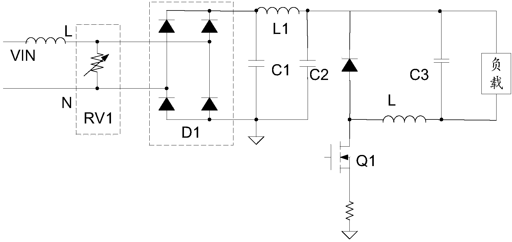
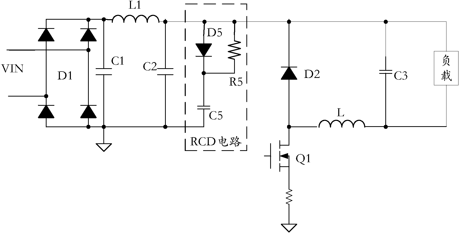
[0068] This embodiment provides a surge protection circuit suitable for a switching power supply. The switching power supply has a main power stage circuit. The main power stage circuit has a main power tube (denoted as Q1), and the main power tube Q1 is coupled to Between the voltage input terminal (denoted as G) of the main power stage circuit and ground, the main power tube Q1 is controlled to be turned on and off to convert the input voltage (denoted as Vg) input to the power stage circuit into the load. Required voltage output. Among them, the specific circuit structure of the switching power supply can be but not limited to Figure 5 , 7 As indicated.

[0069] See Figure 4 As shown, the surge protection circuit of this embodiment mainly includes an input voltage detection circuit 4001 and a switch circuit 4002.

[0070] The input voltage detection circuit 4001 is used to detect the magnitude relationship between the input voltage Vg and the preset threshold voltage, and out...

Embodiment 3

[0080] This embodiment takes the application of the surge protection circuit of this embodiment in a switching power supply as an example, and schematically illustrates the application of the surge protection circuit of this embodiment.

[0081] See Figure 5 As shown, the switching power supply of this embodiment includes a main power stage circuit, and the main power stage circuit mainly includes a main power tube Q1, a rectifier diode D2, an inductor L, and an output capacitor C3.

[0082] Among them, the cathode "-" of the rectifier diode D2, the first end of the output capacitor C3 ( Figure 5 The middle end part A) is commonly connected to the voltage input end G of the main power stage circuit, and the first polarity end of the main power tube Q1 (one of the source "S" or the drain "D", Figure 5 Taking the drain "D" as an example) is connected to the anode "+" of the rectifier diode D2 and the first terminal of the inductor L to be coupled to the voltage input terminal G, and...


PUM


Abstract

The invention discloses a switching power supply and surge protection circuit and a method adaptive to the same. The switching power supply comprises a main power circuit provided with a main power tube. The method includes when the input voltage of the main power circuit is larger than or equal to a voltage threshold, preventing the input energy of the main power circuit from flowing towards the main power tube; when the input voltage of the main power circuit is smaller than the voltage threshold, allowing the input energy to flow towards the main power tube. According to the technical scheme, the main power tube can be protected more effectively, and the efficiency of the switching power supply can be improved effectively.

Description

Technical field [0001] The invention relates to the field of electronics, in particular to a switching power supply and a surge protection circuit and method suitable for the switching power supply. Background technique [0002] Switching Mode Power Supply (English: Switching Mode Power Supply), also known as switching power supply, is a high-frequency electric energy conversion device. Switching power supply is a kind of power supply that uses modern power electronic technology to control the time ratio of switching on and off to maintain a stable output voltage. [0003] Buck switching power supply (step-down switching power supply) is a kind of switching power supply. In Buck switching power supply, if there is a large energy input at the input terminal, that is, when there is an input surge, the generated surge energy will be superimposed on the switching power supply In terms of the input energy of the power stage circuit, the energy on the main power tube (usually: MOSFET sw...

Claims


Application Information

Patent Timeline
Patent Type & Authority Applications(China)
IPC IPC(8): H02M1/32
CPCH02M1/32H02M1/0038H02M1/322
Inventor 陈惠强徐立刚
Owner SILERGY SEMICON TECH (HANGZHOU) CO LTD
Why Eureka
Eureka Blog
Learn More