Zero current detection circuit and DC converter

A zero-current detection and DC converter technology, applied in the field of zero-current detection circuits and DC converters, can solve the problems of power consumption, reverse current cannot output current to contribute, etc., to avoid reverse current and speed up the response Speed, work efficiency improvement effect

Active Publication Date: 2018-02-23
FITIPOWER INTEGRATED TECH INC
View PDF2 Cites 0 Cited by
  • Summary
  • Abstract
  • Description
  • Claims
  • Application Information

AI Technical Summary

Problems solved by technology

When the DC converter works in the discontinuous conduction mode (Discontinuous Conduction Mode, DCM), there will be a reverse current due to the effect of the inductance, and the reverse current cannot contribute to the output current and consumes power

Method used


Image

  • Zero current detection circuit and DC converter
  • Zero current detection circuit and DC converter
  • Zero current detection circuit and DC converter

Examples


Embodiment Construction

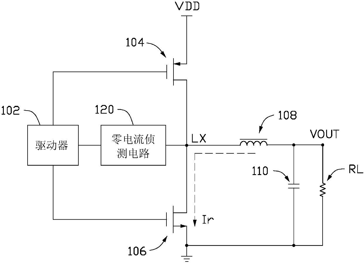
[0066] see figure 1 , figure 1 It is a schematic diagram of the circuit structure of an embodiment of the DC converter 10 of the present invention. The DC converter 10 includes a driver 102 , an upper bridge switch 104 , a lower bridge switch 106 , an inductor 108 , a capacitor 110 , a load RL and an output terminal VOUT. The driver 102 is used to control the on and off of the upper and lower bridge switches 104 , 106 . In this embodiment, the upper bridge switch 104 is a PMOS (P-Metal Oxide Semiconductor) transistor, and the lower bridge switch 106 is an NMOS (N-Metal Oxide Semiconductor) transistor. The source of the upper bridge switch 104 is connected to a voltage source VDD, the drain of the upper bridge switch 104 is connected to the drain of the lower bridge switch 106 , and the source of the lower bridge switch 106 is grounded. The gates of the upper and lower bridge switches 104 , 106 are connected to the driver 102 . The node between the drain of the upper bridge...


PUM


Abstract

The invention provides a zero-current detecting circuit. The zero-current detecting circuit comprises a first current mirror coupled to two transistors, the first transistor is coupled to a grounding end through a first resistor, and the second transistor is coupled to a detection node through a second resistor. The output of the first transistor is coupled to the negative input end of a first comparator, and the output of the second transistor is coupled to the positive input end of the first comparator. When the voltage level of the positive input end of the first comparator is greater than the voltage level of the negative input end of the first comparator, the first comparator outputs a predetermined signal to indicate appearance of zero currents of the detection node.

Description

technical field [0001] The invention relates to a zero current detection circuit and a DC converter using the zero current detection circuit. Background technique [0002] DC converters with upper and lower bridge switches are often used to power CPUs, memory, etc. When the DC converter works in the discontinuous conduction mode (Discontinuous Conduction Mode, DCM), a reverse current is generated due to the effect of the inductance, and the reverse current cannot contribute to the output current and consumes power. Contents of the invention [0003] In view of this, it is necessary to provide a DC converter using a zero current detection circuit to detect and suppress reverse current. [0004] A zero current detection circuit, comprising: [0005] a bias current source; [0006] a current mirror including an input terminal, a first output terminal, a second output terminal and a third output terminal, wherein the input terminal is coupled to the bias current source; ...

Claims


Application Information

Patent Timeline
Patent Type & Authority Patents(China)
IPC IPC(8): H02M7/217
CPCH02M7/217
Inventor 何秋亿李文彦刘益盛
Owner FITIPOWER INTEGRATED TECH INC
Why Eureka
Try Eureka