
Turning mechanism and cabinet turning bed
A technology of overturning mechanism and switching mechanism, which is applied in the direction of beds, bed frames, and other seating furniture, etc. It can solve the problems of unbalanced moment, change of moment arm and moment, etc., to reduce friction, improve safety, and improve stability Effect
- Summary
- Abstract
- Description
- Claims
- Application Information
AI Technical Summary
Problems solved by technology
Method used
Image

Examples
Embodiment Construction
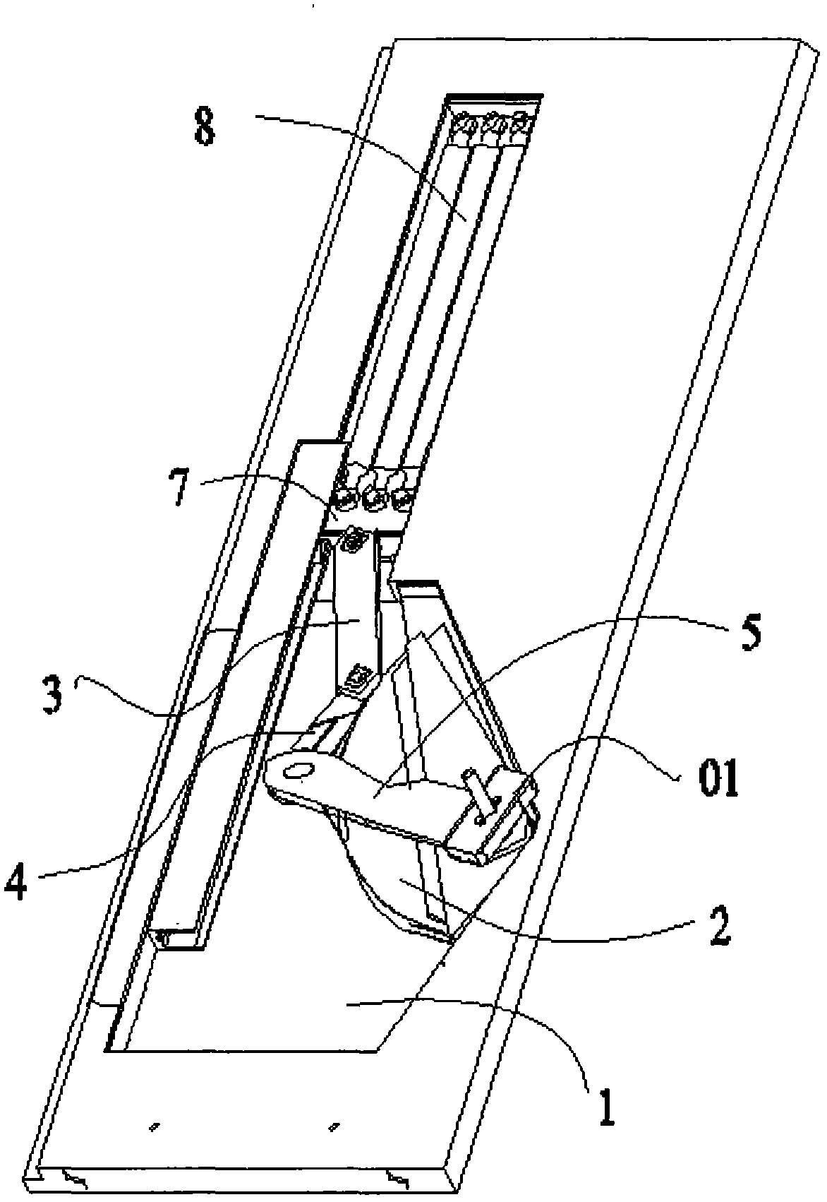
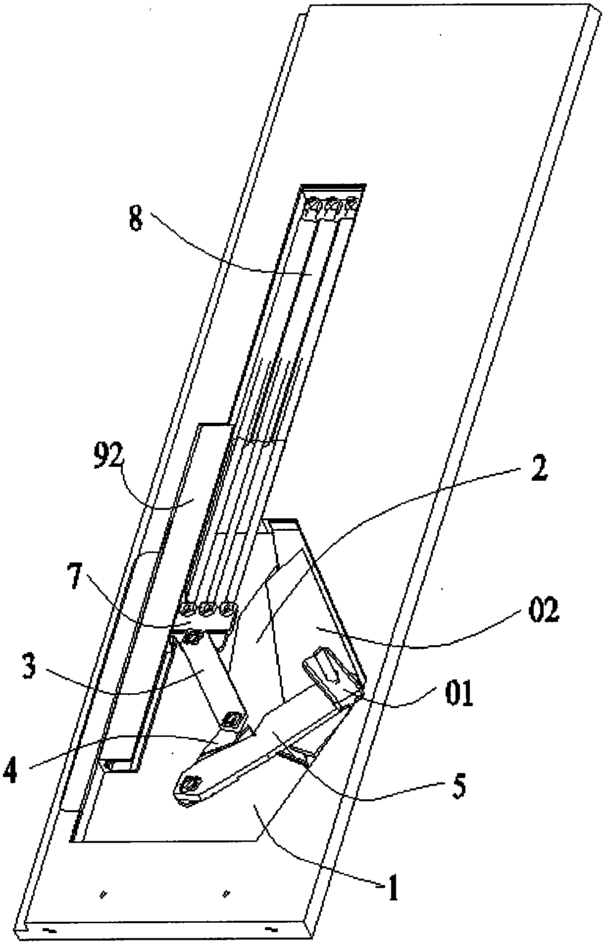
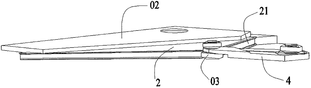
[0030] The following will be combined with figure 1 To attach Figure 5 The present invention is further described, but it should not be used to limit the protection scope of the present invention.
[0031] In order to facilitate the description and understanding of the technical solution of the present invention, the orientation words used in the following description are all subject to the orientation shown in the drawings.
[0032] control figure 1 To attach Figure 4 , a turning mechanism, including a bottom plate 1, a curve moment adjustment device 2 is set on the right side of the bottom plate, the curve moment adjustment device 2 is generally fan-shaped structure, and a curve guide rail 21 is arranged on the curve moment adjustment device 2. The third connecting rod 5 is rotated on the right side of the curve moment adjusting device 2, and the third connecting rod 5 is connected to the second connecting rod 4 in rotation, and the second connecting rod 4 is connected ...
PUM
 Abstract
Description
Claims
Application Information