Washing Machine Driving Apparatus And Washing Machine Including Same

A technology for driving devices and washing machines, applied in the field of washing machines and washing machine driving devices, can solve the problems of reducing space utilization, increasing production costs, interference, etc., and achieve the effects of improving performance, increasing space utilization, and preventing interference

Active Publication Date: 2017-02-22
AMOTECH
View PDF9 Cites 2 Cited by
  • Summary
  • Abstract
  • Description
  • Claims
  • Application Information

AI Technical Summary

Problems solved by technology

[0004] However, conventional washing machines required planetary gear fingers, clutches, etc. to selectively rotate the pulsator and the inner tank, resulting in complicated structures and increased manufacturing costs.
[0005] Moreover, in conventional washing machines, a planetary gear device and a clutch are provided between the drive motor and the outer tank, so the area occupied by the washing machine in the height direction becomes larger, and thus the height of the washing machine becomes higher, or the washing machine has the same height. In some cases, it is necessary to reduce the height of the inner tank, so there is a problem that the washing capacity decreases
[0006] In addition, the conventional washing machine has a structure that only rotates the pulsator and the inner tank in the same direction, so that the pulsator and the inner tank cannot be rotated in opposite directions. There is a limit to the improvement of the performance of the washing machine.
[0007] In addition, in the conventional drive motor, the rotor is exposed to the outside, so there is a possibility of interference with other components. Therefore, it is necessary to maintain a sufficient distance between the drive motor and other components to avoid interference, so there is room for reduction. The question of usability

Method used


Image

  • Washing Machine Driving Apparatus And Washing Machine Including Same
  • Washing Machine Driving Apparatus And Washing Machine Including Same
  • Washing Machine Driving Apparatus And Washing Machine Including Same

Examples


Embodiment Construction

[0038] Hereinafter, embodiments of the present invention will be described in detail with reference to the drawings. In this process, the size or shape of the structural elements shown in the figure can be enlarged for clarity and convenience of description. In addition, considering the structure and function of the present invention, the specially defined terms can be changed according to the intention or management of the users and operators. The above-mentioned terms are defined based on the entire content of this specification.

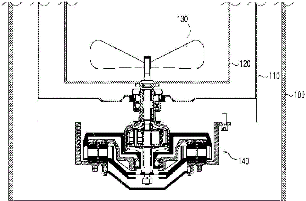
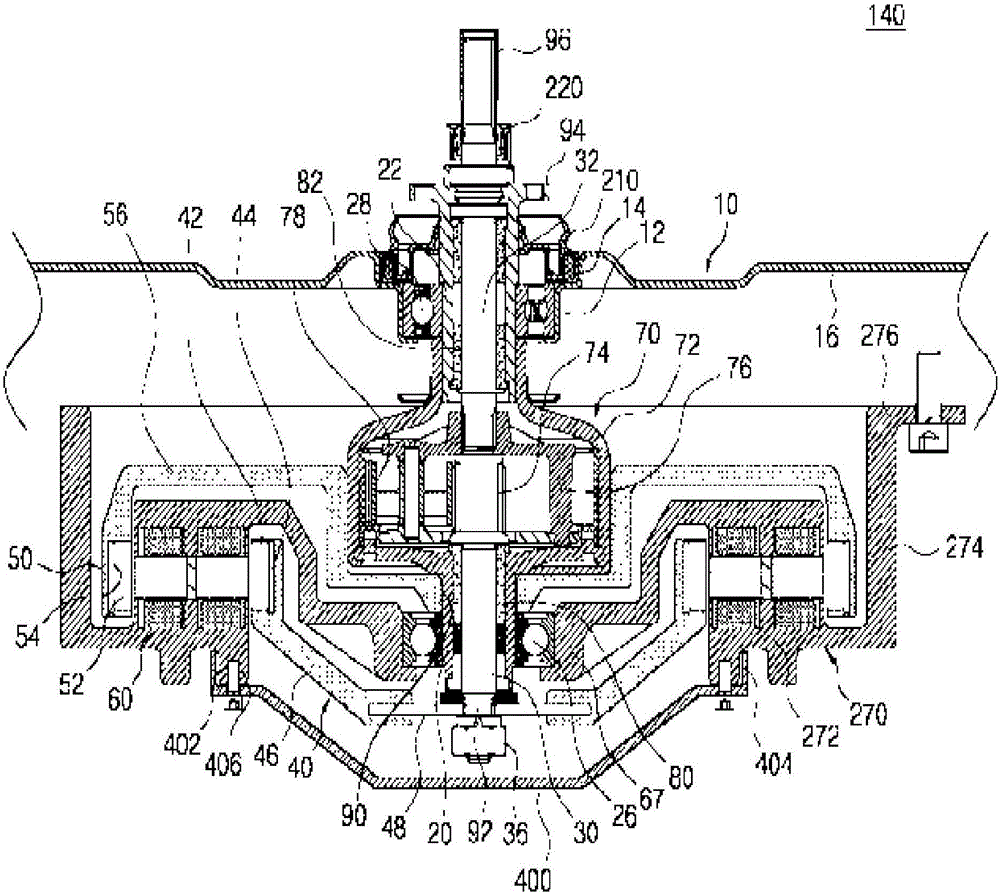
[0039] figure 1 It is a cross-sectional view of a washing machine according to an embodiment of the present invention. figure 2 It is a cross-sectional view of a washing machine driving device according to an embodiment of the present invention.

[0040] Reference figure 1 , The washing machine of the present invention includes: a housing 100 for forming an outer shape; an outer tank 110, which is arranged inside the housing 100, for containing washi...


PUM


Abstract

A washing machine driving apparatus of the present invention comprises: a double rotor-double stator type of drive motor that includes an inner rotor and an outer rotor that can be independently controlled by double stators and selectively generates an inner-rotor output and an outer-rotor output; a first inner shaft that transfers the inner-rotor output as a first input; a first outer shaft that is coupled to the outer periphery of the first inner shaft so as to be rotatable and transfers the outer-rotor output as a second input; a planetary gear device in which a gear ratio of a transmission output generated from a carrier when the first input is applied to a sun gear through the first inner shaft is controlled by the second input applied to a ring gear through the first outer shaft; and a protection unit for protecting the inner rotor, wherein the outer periphery of the protection unit is supported by the double stators. As a result, interference between the rotors and other components can be prevented so that the other components can be installed at a close location to the motor, thereby making better use of a space.

Description

Technical field [0001] The invention relates to a washing machine driving device with an inner rotor and an outer rotor independently driven and a washing machine having the same. Background technique [0002] As disclosed in the Korean Patent Publication No. 10-0548310 (January 24, 2006), the conventional washing machine includes: an outer shell for forming an outer shape; an outer tank, which is supported by the inside of the outer shell, for containing washing water inside; The inner tank for both washing and dehydration is housed in the outer tank in a rotatable manner; the pulsator is rotatably installed in the inner tank to form a washing water flow; the drive motor is used for Generating the driving force to rotate the inner groove and the pulsator; the inner groove rotating shaft receives the driving force of the driving motor to rotate the inner groove; the pulsator rotating shaft receives the driving force of the driving motor to rotate the pulsator; The sun gear is co...

Claims


Application Information

Patent Timeline
Patent Type & Authority Applications(China)
IPC IPC(8): H02K16/02H02K7/116D06F37/20D06F37/30
CPCH02K7/116H02K2213/12D06F37/40H02K16/00D06F37/30D06F37/304D06F37/20H02K7/10H02K16/02H02K7/003D06F23/04D06F37/12D06F37/206D06F37/26
Inventor 金炳秀高亨焕金学录李世基
Owner AMOTECH
Why Eureka
Try Eureka