Al technical title is built by PatSnap Al team. It summarizes the technical point description of the patent document.
A high-torque, bolting machine technology, applied in the installation of bolts, rotary drilling rigs, drilling equipment and methods, etc., can solve the problems of non-switchable torque, inconvenient operation and use, etc., to achieve the effect of changing torque and stable equipment
Active Publication Date: 2018-11-16
JIKAI HEBEI MECHATRONICS TECH CO LTD
View PDF13 Cites 3 Cited by
Summary
Abstract
Description
Claims
Application Information
AI Technical Summary
This helps you quickly interpret patents by identifying the three key elements:
Problems solved by technology
Method used
Benefits of technology
Problems solved by technology
[0003] However, there are many deficiencies in the current bolter. For example, the traditional bolter cannot switch the torque, which is not easy to operate and use. Therefore, a new type of high-torque bolter is proposed to solve the above problems.
Method used
Image
Click on the blue label to locate the original text in one second.
Reading with bidirectional positioning of images and text.
Examples
Embodiment Construction
[0014] The following will clearly and completely describe the technical solutions in the embodiments of the present invention with reference to the accompanying drawings in the embodiments of the present invention. Obviously, the described embodiments are only some, not all, embodiments of the present invention. Based on the embodiments of the present invention, all other embodiments obtained by persons of ordinary skill in the art without making creative efforts belong to the protection scope of the present invention.
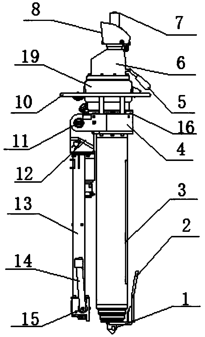
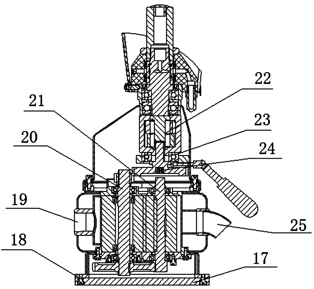
[0015] see Figure 1~2 , a new type of high-torque bolter, including a leg 3 and a top 1 installed at the bottom of the leg 3, the leg 3 is a cylindrical structure, and the top of the leg 3 is provided with a fixed sleeve 4, so The supporting leg 3 is detachably connected with the fixed sleeve 4, the fixed sleeve 4 is connected with the three-way valve body 12 through the speed regulating shaft 11, the three-way valve body 12 is a hollow cylinder structure, an...
PUM
Abstract
The invention discloses a novel large torque roof bolter. The novel large torque roof bolter includes a tip, a handle, a landing leg, a fixing sleeve, a conversion handle, a reduction box shell, a drill sleeve, a water blocking sleeve, a motor shell, a support ring, a regulating shaft, a fixing sleeve, an operating arm, a support plate, a handle frame, a back cover plate, a cylinder head inner hexagon screw, an air inlet, an auxiliary shaft, a drive gear shaft, a main shaft, a bearing, and an air outlet. The tip is arranged at the bottom end of a base, equipment is convenient to fix. The landing leg is arranged at the top end of the base, the fixing sleeve is arranged at the top end of the handing leg, the fixing sleeve fastens the landing leg and the back cover plate, so that the equipment is steadier. The fixing sleeve is rotationally connected with the fixing sleeve through the regulating shaft, the operating arm is arranged in the fixing sleeve, and the equipment is convenient to operate. The air inlet is arranged at the top end of the back cover plate, and the air outlet is arranged at the position, depart from one end of the air inlet, of the top end of the base plate. The air outlet drives the auxiliary shaft and the drive gear shaft to rotate, the gear is arranged at the top end of the drive gear shaft, the angle of the conversion handle is rotated, and the position ofthe gear can be changed, so that the effect of changing torque is achieved.
Description
technical field [0001] The invention relates to a bolter, in particular to a novel high-torque bolter, which belongs to the technical field of machinery. Background technique [0002] Bolting machine, also known as soil nailing machine, bolting rig or pneumatic impact machine, is mainly used for rock and soil bolting, roadbed, slope treatment, underground deep foundation pit support, tunnel surrounding rock stability, prevention of landslides and other disasters. Underground engineering support and high-rise building foundation treatment, also suitable for deep foundation pit spray protection, non-prestressed bolt support for slope soil nailing engineering. [0003] However, there are many deficiencies in the current bolter, such as the non-switchable torque of the traditional bolter, which is not easy to operate and use. Therefore, a new type of high-torque bolter is proposed to solve the above problems. Contents of the invention [0004] The object of the present invent...
Claims
Application Information
Patent Timeline
Application Date:The date an application was filed.
Publication Date:The date a patent or application was officially published.
First Publication Date:The earliest publication date of a patent with the same application number.
Issue Date:Publication date of the patent grant document.
PCT Entry Date:The Entry date of PCT National Phase.
Estimated Expiry Date:The statutory expiry date of a patent right according to the Patent Law, and it is the longest term of protection that the patent right can achieve without the termination of the patent right due to other reasons(Term extension factor has been taken into account ).
Invalid Date:Actual expiry date is based on effective date or publication date of legal transaction data of invalid patent.