Apparatus for fastening a handle on a power tool

a technology for power tools and accessories, applied in the field of accessories, can solve the problems of unintentional rotation of the grip, power tool loosening of the clamping ring, and difficulty in adjusting the grip

Active Publication Date: 2013-04-02
ROBERT BOSCH GMBH
View PDF8 Cites 27 Cited by
  • Summary
  • Abstract
  • Description
  • Claims
  • Application Information

AI Technical Summary

Benefits of technology

[0010]It is especially advantageous in this respect if the tension lever is coupled with a spring element, and the spring element, as a function of the position of the tension lever, has at least two stable positions, of which one stable position is the fastening position. As a result, two stable positions of the apparatus on the power tool are achieved, for instance the fastening position and the position for adjusting the radial position of the apparatus on the power tool, which can be changed without having to actuate the tension lever.
[0011]It is especially advantageous in this respect if in the fastening position, the tension lever rests flush on a contour of the device. As a result, it is made visually apparent that the device is in a stable position and at the same time, the clamping element is prevented for instance from striking other objects and thus causing an unintentional adjustment.
[0014]To make it possible for the apparatus to be used also on power tools that were not originally intended for receiving an apparatus of the invention for positioning and fastening it, it is also possible in an advantageous embodiment for the receptacle geometry to be embodied on a component embodied separately, as a retaining ring which is connected to the power tool.
[0015]However, it is especially advantageous if the receptacle geometry is embodied integrally with the power tool. As a result, the apparatus is especially compact, and no additional devices for fastening the receptacle geometry to the power tool are necessary.
[0017]In this respect it is especially advantageous if a continuous transition from the side of the retaining collars to the level of the retaining collars is embodied without longitudinal ribs. As a result, it becomes possible for the apparatus to be connected to the power tool without requiring that the tension lever be additionally opened manually.

Problems solved by technology

However, such an embodiment has many different parts, and the clamping requires an undesirable screwing operation.
Although the number of parts is reduced in this embodiment, nevertheless it can in particular happen that in heavy-duty use of the power tool, the grip is unintentionally rotated, causing the clamping ring to come loose from the power tool.
This can result in dangerous situations for a user of the handle.

Method used


Image

  • Apparatus for fastening a handle on a power tool
  • Apparatus for fastening a handle on a power tool
  • Apparatus for fastening a handle on a power tool

Examples


Embodiment Construction

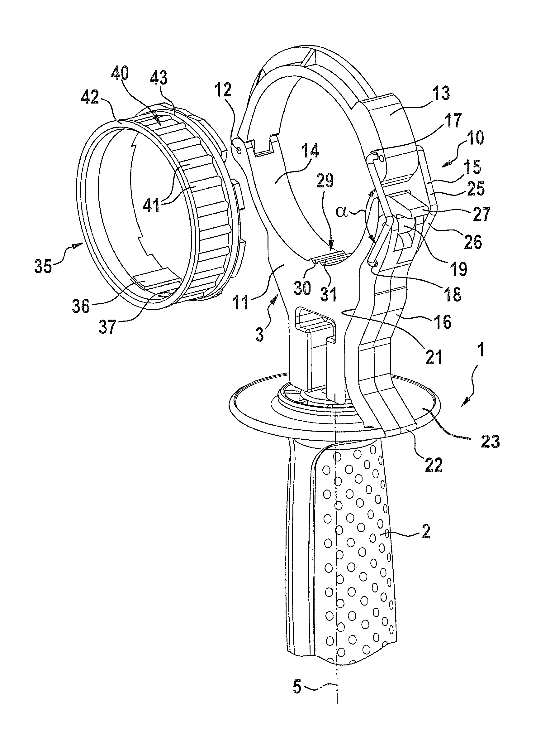
[0022]In FIG. 1, a device embodied as a handle 1 is shown. The handle 1 can be connected to a power tool, not shown, and serves as an additional way for a user to hold the power tool, so that when torque occurs, and given the weight of the power tool, the user can brace it better and guide it more precisely.

[0023]The handle 1 has a lower region, embodied as a grip 2, which is connected to an upper retaining region 3. Both the grip 2 and the retaining region 3 comprise metal or plastic. The grip 2 can also preferably be positioned in various radial positions relative to the retaining region 3 with respect to a longitudinal axis 5.

[0024]The retaining region 3 includes an apparatus 10 for positioning and fastening the handle 1 to the power tool. The retaining region 3 has a lower tool receptacle 11, which via a first joint 12 is connected pivotably to an upper tool receptacle 13. By the lower receptacle 11 and the upper receptacle 13, a receptacle 14 for the power tool is embodied that...


PUM

PropertyMeasurementUnit
angleaaaaaaaaaa
tensionaaaaaaaaaa
spring forceaaaaaaaaaa

Abstract

The invention relates to an apparatus for positioning and fastening a device, in particular of a handle on a power tool. The apparatus includes a receptacle for the device, which receptacle is adjustable between at least one positioning position and at least one fastening position. The at least two positions of the device are definable by a tension lever. A detent geometry, embodied with the receptacle, cooperates with a receptacle geometry, embodied on or associated with the power tool. Various radial positions of the apparatus relative to the power tool can be set by the detent geometry and the receptacle geometry. According to the invention, it is provided that in addition, an axial securing device associated with the apparatus or the power tool, is provided, which in the positioning position and the fastening position secures the apparatus in its axial position relative to the power tool.

Description

CROSS-REFERENCE TO RELATED APPLICATION[0001]This application is based on German Patent Application 10 2009 027 570.3 filed Jul. 9, 2009.BACKGROUND OF THE INVENTION[0002]1. Field of the Invention[0003]The present invention relates to an apparatus, in particular for positioning and fastening a device, in particular a handle on a power tool.[0004]2. Description of the Prior Art[0005]One such apparatus is known from German Patent Application DE 10 2008 000 158 A1, which was not published prior to the filing date of the present application. The known apparatus has a handle, with a clamping ring which is fastened to the handle and on the inside circumference of which longitudinal ribs are formed that cooperate with corresponding complementary geometries on a power tool. The clamping ring is movable on the handle by means of a tension lever between a first position, in which the power tool can be put into operative connection with the clamping ring, and the second position for fixation of ...

Claims


Application Information

Patent Timeline
Patent Type & Authority Patents(United States)
IPC IPC(8): B25G1/00A45C13/26
CPCB25F5/026Y10T16/4713Y10T16/469B23B45/001B23B45/003B25G1/002
Inventor BRENNENSTUHL, JENSROEHM, HEIKOSCHLEGL, STEFAN
Owner ROBERT BOSCH GMBH
Why Eureka
Try Eureka