Device connector

a technology for connecting devices and devices, applied in the direction of three-pole connections, coupling device connections, securing/insulating coupling contact members, etc., to achieve the effect of preventing crack formation in another synthetic resin portion, increasing spacing, and easy change of positions

Inactive Publication Date: 2012-05-29
SUMITOMO WIRING SYST LTD
View PDF8 Cites 26 Cited by
  • Summary
  • Abstract
  • Description
  • Claims
  • Application Information

AI Technical Summary

Benefits of technology

[0011]An endless ring-shaped seal preferably is provided on a surface of the housing facing the case. The seal surrounds the terminal fittings in a looped manner, and prevents water from penetrating between the case and the device connector.
[0012]The device mounting portions may be in one or more mounting pieces projecting from an outer peripheral edge of the reinforcing plate. Accordingly, it is possible to increase spacings between the terminal fittings and easily change the positions of the terminal fittings by enlarging the opening for permitting the passage of the terminal fittings.
[0013]A part of the reinforcing plate covered by the synthetic resin of the housing may be formed with one or more anchor grooves. The synthetic resin that covers the reinforcing plate enters the anchor grooves and adheres to the reinforcing plate in shrinking directions. Thus, the synthetic resin covering the reinforcing plate will not shrink in a biased manner, and crack formation in another synthetic resin portion is prevented.
[0014]A part of the reinforcing plate covered by the synthetic resin of the housing may have one or more connection holes. The synthetic resin that covers the reinforcing plate enters the connection holes to connect layers of the synthetic resin on the opposite surfaces of the reinforcing plate and to adhere to the reinforcing plate in shrinking directions. Thus, the synthetic resin covering the reinforcing plate will not shrink in a biased manner and crack formation in another synthetic resin portion is prevented.

Problems solved by technology

However, synthetic resin is not present on the outer peripheral end surface of the reinforcing plate, and hence there is no synthetic resin to be pulled and cracked as the synthetic resin covering the opposite surfaces of the reinforcing plate shrinks.

Method used


Image

  • Device connector
  • Device connector
  • Device connector

Examples


first embodiment

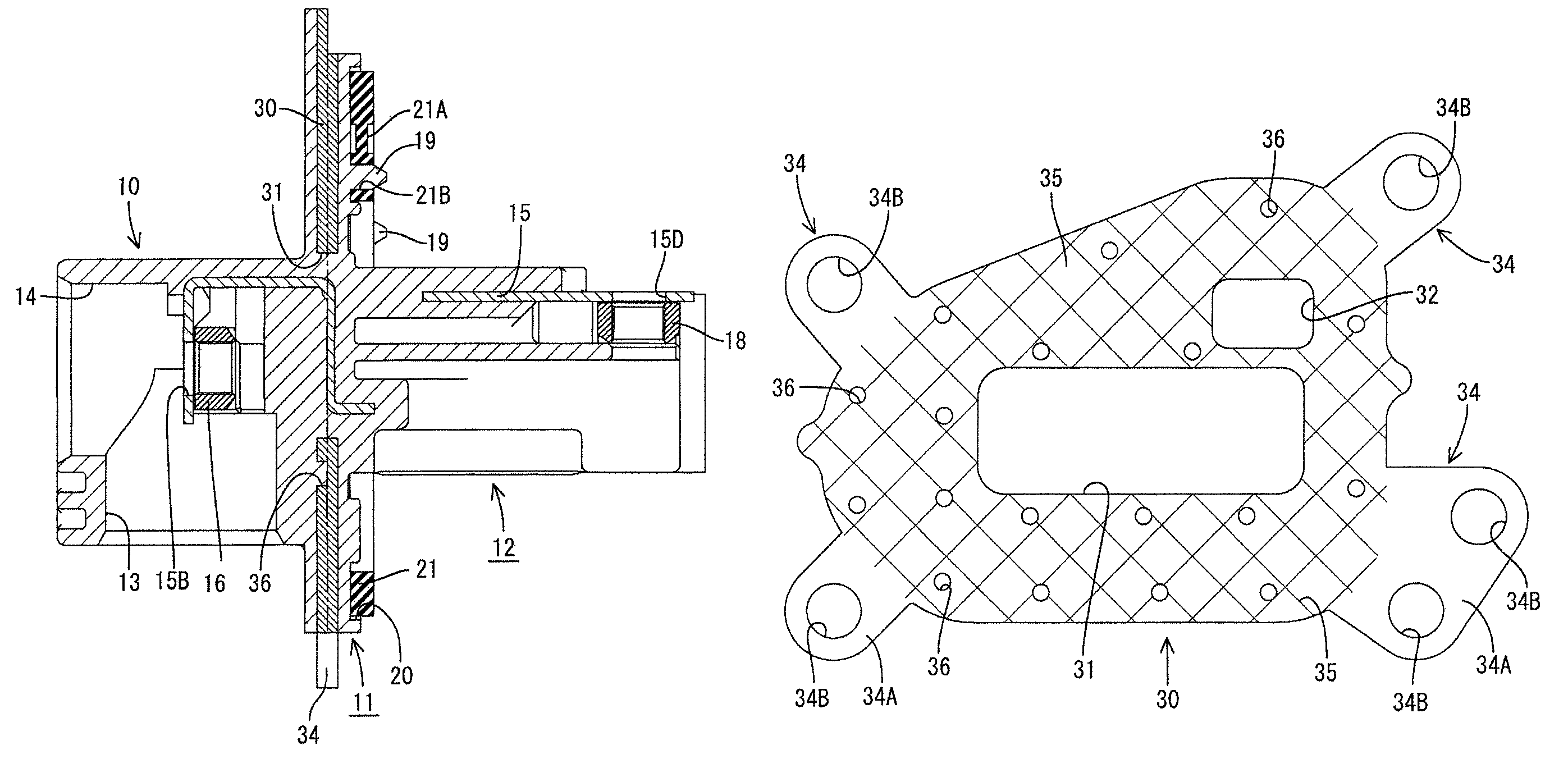
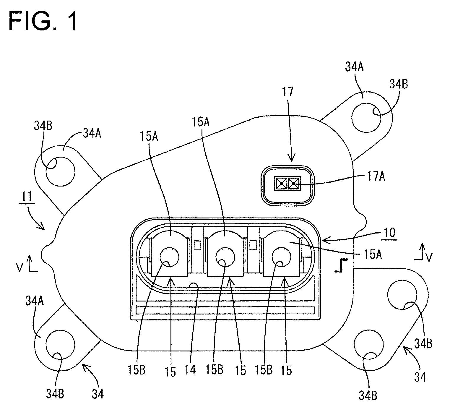
[0030]A device connector according to the invention is illustrated in FIGS. 1 to 7. The device connector is to be mounted in a connector mounting portion (not shown) provided in a case of a device. An end toward a mating connector and an end toward the connector mounting portion in the case of the device are referred to respectively herein as the front and rear ends in the following description.

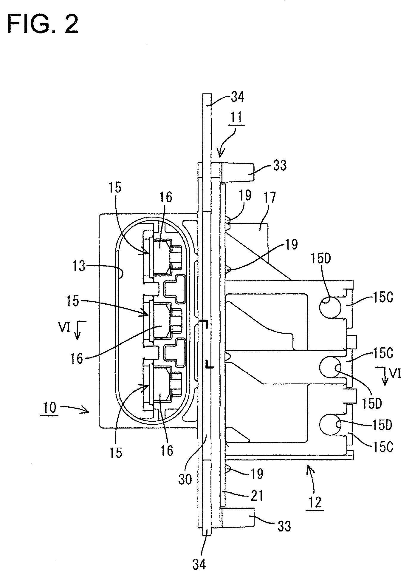
[0031]As shown in FIGS. 1 to 6, the device connector has a housing main body 10 substantially in the form of a rectangular parallelepiped extending in a forward direction. A flange 11 extends out from the outer peripheral surface of a rear part of the housing main body 10 and is substantially normal to the forward direction. A device-side housing portion 12 extends back from the rear surface of the flange 11 and can be accommodated in a connector mounting hole (not shown) formed e.g. in the case of the device. The housing main body 10, the flange 11 and the device-side housing portion 12 show...

second embodiment

[0047]The device connector of the second embodiment has a housing main body 10 and a device-side housing portion 12 on opposite sides of a substantially rectangular flange 11. The positions of a fitting portion 13 and a work hole 14 in the housing main body 10 are switched or inverted and terminal fittings 15 are held in to extend substantially straight back.

[0048]The three terminal fittings 15 held in the device-side housing portion 12 are arranged substantially side by side. Thus, the terminal fittings 15 connecting the housing main body 10 and the device-side housing portion 12 extend substantially on the same plane although being slightly bent in the device-side housing portion 12.

[0049]An auxiliary housing 17 extends in forward and backward directions via the flange 11 and is formed such that surfaces thereof before the flange 11 and those after the flange 11 are shifted somewhat laterally. A connection detecting terminal 17A held in the auxiliary housing 17 also is bent accord...


PUM


Abstract

A device connector has a housing main body (10), a device-side housing portion (12) to be accommodated in a connector mounting hole, a reinforcing plate (30) including an opening (31) for permitting the passage of terminal fittings, and a flange (11) formed by insert molding using the reinforcing plate (30) and synthetic resin, and terminal fittings 15. An outer peripheral end surface of the reinforcing plate (30) is exposed. The device connector is produced with a reduced cost by insert molding using a metal reinforcing plate as an insert while preventing a crack from being created in a synthetic resin portion covering the reinforcing plate (30).

Description

BACKGROUND OF THE INVENTION[0001]1. Field of the Invention[0002]The invention relates to a connector to be mounted in a case of a device.[0003]2. Description of the Related Art[0004]U.S. Pat. No. 7,572,150 discloses a device connector for connecting a wire-side connector with a device. The wire-side connector is mounted on an end of a wire extending from a power supply. The device is a motor in a metal case of an electric vehicle. The device connector has a housing made of synthetic resin and formed by insert molding using terminal fittings as inserts. The housing is mounted in an aluminum die-cast shell. The die-cast shell has mounting pieces that receive bolts to mount the device connector in the device.[0005]The aluminum die-cast shell of the conventional device connector is strong but costly. Studies in recent years have tried to develop a sufficiently strong cost efficient device connector by molding a resin housing with a metal reinforcing plate as an insert. However, the synt...

Claims


Application Information

Patent Timeline
Patent Type & Authority Patents(United States)
IPC IPC(8): H01R13/73
CPCH01R13/504H01R13/5202H01R13/707H01R4/34H01R13/748H01R2105/00
Inventor MATSUOKA, HIROYUKINAKAGAWA, DAISUKE
Owner SUMITOMO WIRING SYST LTD
Why Eureka
Try Eureka