
Chemical liquid supply method and apparatus thereof

a liquid supply method and liquid supply technology, applied in liquid separation auxilary devices, liquid fuel engine components, water/sewage treatment by degassing, etc., can solve the problems of deteriorating manufacturing yield of semiconductor integrated circuit devices, and achieve the effect of improving cleanliness

Inactive Publication Date: 2001-05-29
KOGANEI
View PDF7 Cites 106 Cited by
  • Summary
  • Abstract
  • Description
  • Claims
  • Application Information

AI Technical Summary

Benefits of technology

An object of the present invention is to provide a chemical liquid supply method and a chemical liquid supply apparatus which remove impure portions such as air bubbles and gelled portions from the liquid, so that a liquid can be discharged with improved cleanliness.
According to the present invention, a filter is provided on the primary side of a pump, and a liquid is filtered during the sucking operation of the pump. During the discharging operation, the liquid does not pass through the filter. As a result of this, the flow speed of the liquid filtered after passing through the filter and the discharge flow speed of the liquid discharged from the liquid discharge portion can be set to differ from each other. By making the flow speed lower than the discharge flow speed, the sucking operation of the pump can be performed slowly, so that the impure portions such as gelled portions and air bubbles can be prevented from permeating through the filter.
In this manner, an extent of the cleanliness of the discharged liquid can be improved. If the chemical liquid supply technique of the present invention is adopted in the step of manufacture a semiconductor integrated circuit device, the manufacturing yield on semiconductor integrated circuit devices can be improved.
By returning the liquid discharged from the pump to the filter through a return path with use of one single pump, it is possible to exhaust securely air bubbles contained in the liquid with a simple structure.
Since the pump operation speed for permeating the liquid through the filter and the pump operation speed for discharging the liquid from the pump outlet can be controlled independently, it is possible to obtain an accurate discharged from amount or an accurate discharge flow rate without being influenced from pressure loss caused by the filter. In addition, the speed of the liquid passing through the filter and the discharge speed of the liquid discharged from a discharge portion can be separately set to optimum values, respectively.
Also, since a plurality of chemical liquid supply units layered or integrated onto a mother board can be detachably attached, the space on the mother board can be improved efficiently by connecting pipes concentrated onto the mother board. In addition, several lines that can be used in common among various lines such as power lines, signal lines, gas lines, liquid lines, and the like provided in form of one system with respect to the mother board.

Problems solved by technology

If the gelled foreign substance is coated onto the semiconductor wafer, the manufacturing yield on the semiconductor integrated circuit device is deteriorated.

Method used


Image

  • Chemical liquid supply method and apparatus thereof
  • Chemical liquid supply method and apparatus thereof
  • Chemical liquid supply method and apparatus thereof

Examples


Embodiment Construction

In the following, embodiments of the present invention will be specifically explained on the basis of the drawings.

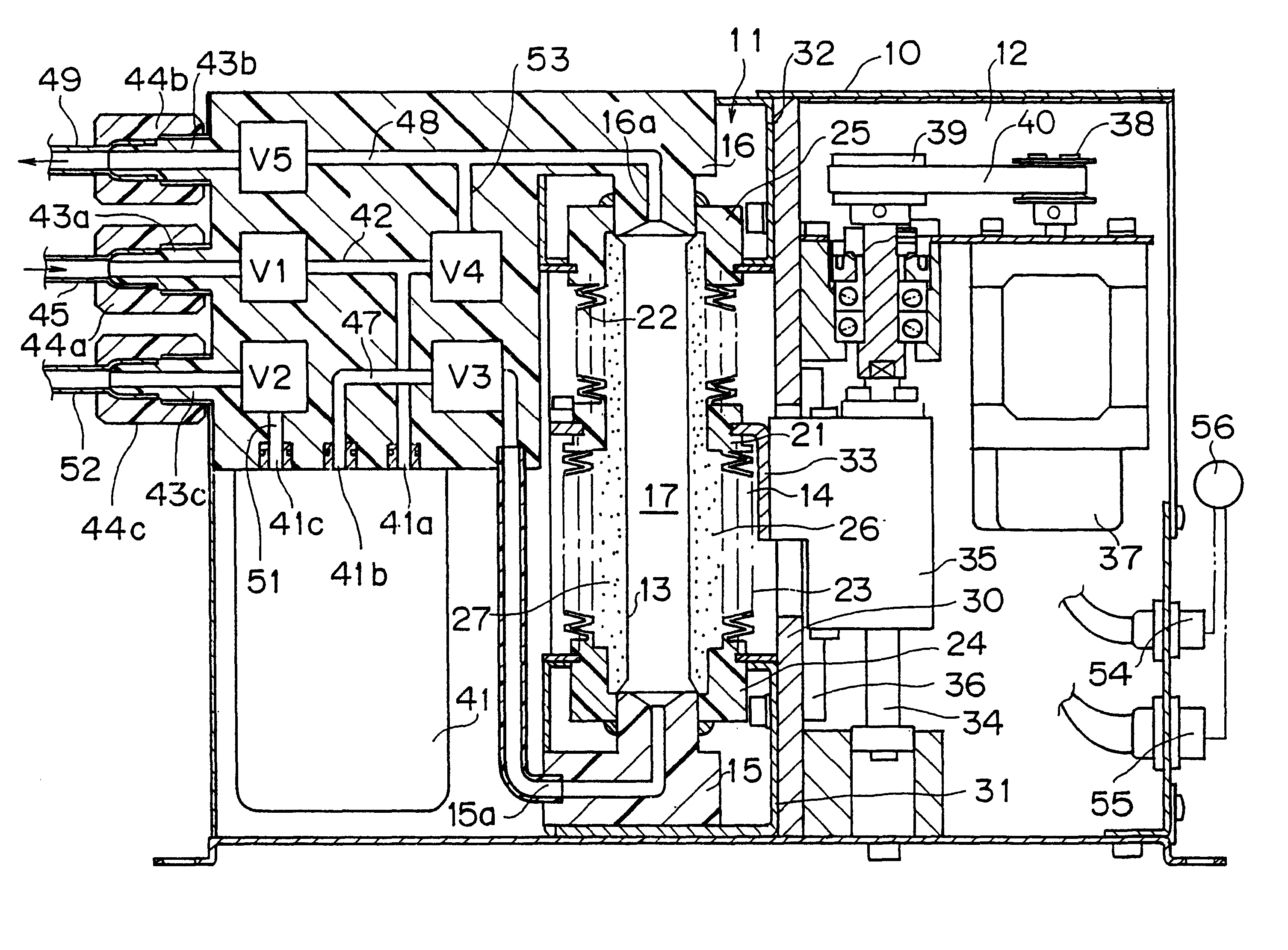
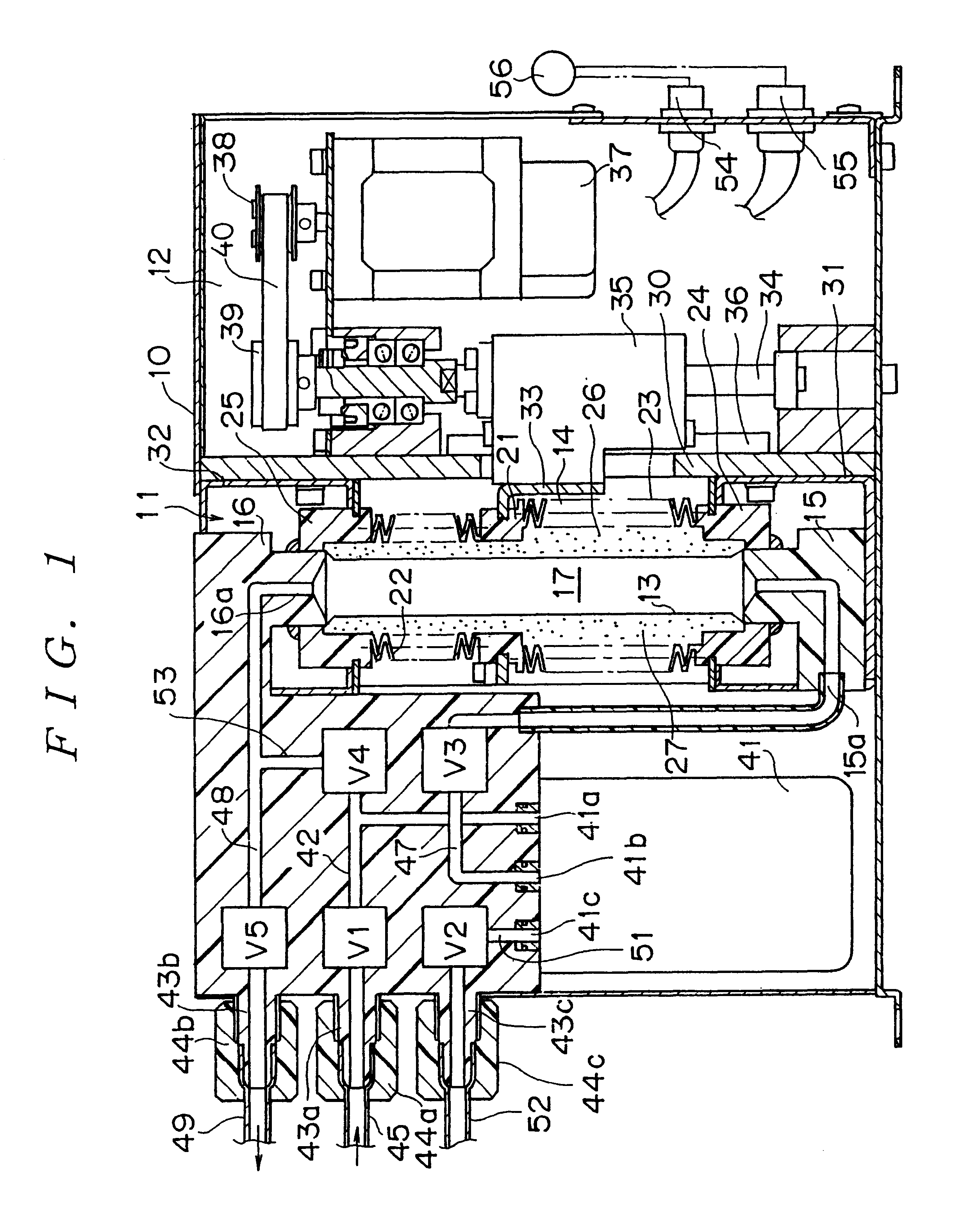
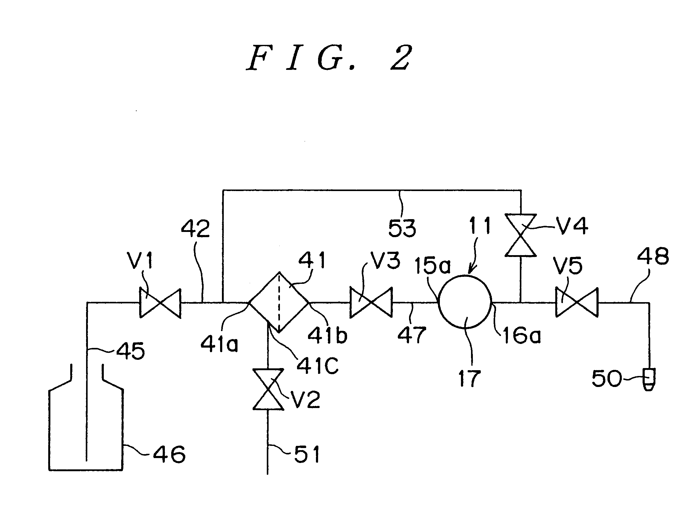
FIG. 1 is a cross-sectional view showing a chemical liquid supply apparatus as an embodiment of the present invention. FIG. 2 is a liquid circuit diagram schematically showing flow of a liquid in the chemical liquid supply apparatus shown in FIG. 1. FIG. 3 is an enlarged cross-sectional view of a pump section shown in FIG. 1.

This chemical liquid supply apparatus has a pump 11 and a pump drive section 12 which are assembled in a housing 10. The pump 11 comprises a flexible tube 13 which is made of an elastic material and is elastically expandable and contractible in the radial direction, and a bellows 14 which is provided outside the tube and is made of an elastic material to be elastically deformable in the axial direction.

An inlet-side adapter 15 is attached to an end portion of the flexible tube 13, and an outlet-side adapter 16 is attached to another end portion of t...


PUM

PropertyMeasurementUnit
Flow rateaaaaaaaaaa
Speedaaaaaaaaaa

Abstract

Impure portions such as air bubbles and gelled portions in a liquid are removed so that the liquid can be discharged with improved cleanliness. Under condition that a return flow path and a liquid discharge flow path are closed, a pump chamber is expanded, thereby sucking the liquid in a liquid container portion into a pump chamber through a filter. Under condition that a vent port of the filter and the return flow path are opened and a liquid introducing flow path, the liquid discharge flow path, and a pump inlet flow path are closed, the pump chamber is contracted, thereby returning the liquid in the pump chamber toward the filter so that air in the filter is exhausted to the outside. Under condition that the return flow path and the pump inlet flow path are closed, the pump chamber is contracted, thereby discharging the liquid from the nozzle.

Description

The present invention relates to a chemical liquid supply technique of discharging a predetermined amount of liquid from a chemical liquid or the like, which is preferably used to coat a processing liquid such as a photoresist liquid or the like onto a surface of a semiconductor wafer.Chemical liquid such as photoresist liquid, spin on glass liquid, polyimide resin liquid, pure water, developing liquid, etching liquid, washing liquid, organic solvent, and the like are used in manufacturing processes in various technical fields such as techniques of manufacturing a liquid crystal board, a magnetic disk, a multi-layered wiring board, and the like, starting from a semiconductor wafer manufacturing technique.For example, in case of coating a photoresist liquid onto the surface of the semiconductor wafer, the photoresist liquid is dropped onto the surface of the semiconductor wafer from a nozzle, after having rotated the semiconductor wafer in the horizontal plane. In a chemical liquid s...

Claims


Application Information

Patent Timeline
IPC IPC(8): B01D37/00B01D36/00B01D37/04B01D35/26B01D35/00F04B43/10F04B43/107F04B43/00C02F1/20B05C11/10F04B15/00G03F7/16H01L21/027
CPCB01D35/26B01D36/001B01D37/04F04B43/10F04B43/107C02F1/20
Inventor YAJIMA, TAKEO
Owner KOGANEI
Learn More