Industrial fabric, and method of making thereof

a technology of industrial fabrics and fabric layers, applied in the field of endless structures, can solve the problems of high processing costs, high processing costs, and low bulk in the finished product, and achieve the effects of low cost, low cost of rolling, and high processing cos

Active Publication Date: 2014-09-02
ALBANY INT CORP
View PDF136 Cites 105 Cited by
  • Summary
  • Abstract
  • Description
  • Claims
  • Application Information

AI Technical Summary

Benefits of technology

[0020]The instant invention provides an improved fabric, belt, or sleeve that functions in place of a traditional fabric, belt, or sleeve, and aids in imparting desired physical characteristics, such as bulk, appearance, texture, absorbency, strength, and hand to the nonwoven products produced thereon.
[0021]Other advantages such as, but not limited to, more effective wet shaping; an improved web release over prior art woven fabrics as a result of no yarn crossovers like in woven fabrics to trap elementary fibers; and easier cleanability are provided.
[0025]One embodiment relates to a support member such as a belt or sleeve for supporting and conveying polymeric fibers in a spunlace or hydroentanglement process. Many nonwoven products are calendared after being formed in a second process. During that process, one calendar roll (or both) may have a pattern on the surface that is used to impart a texture to the nonwoven. The instant inventive belts or sleeves exhibit the following non-limiting advantages over this separate calendaring process: sleeves are a relatively less expense item with no large capital investment in fixed equipment; patterning is accomplished during the forming process itself, eliminating the need for a separate additional process; lower material content in the final product can be achieved as product caliper is not reduced from compression due to calendaring; the finished product can be produced with high bulk as it is not compressed at any stage. To the nonwoven rolled-goods producer, these process advantages further lead to the end product advantages of: lower cost spunlace or hydroentangled webs with patterns or marks; the ability to customize products as the volume justification for patterns is greatly reduced; production of higher performance products as high bulk imparts the characteristic of higher absorbency, which is of great value in consumer applications.
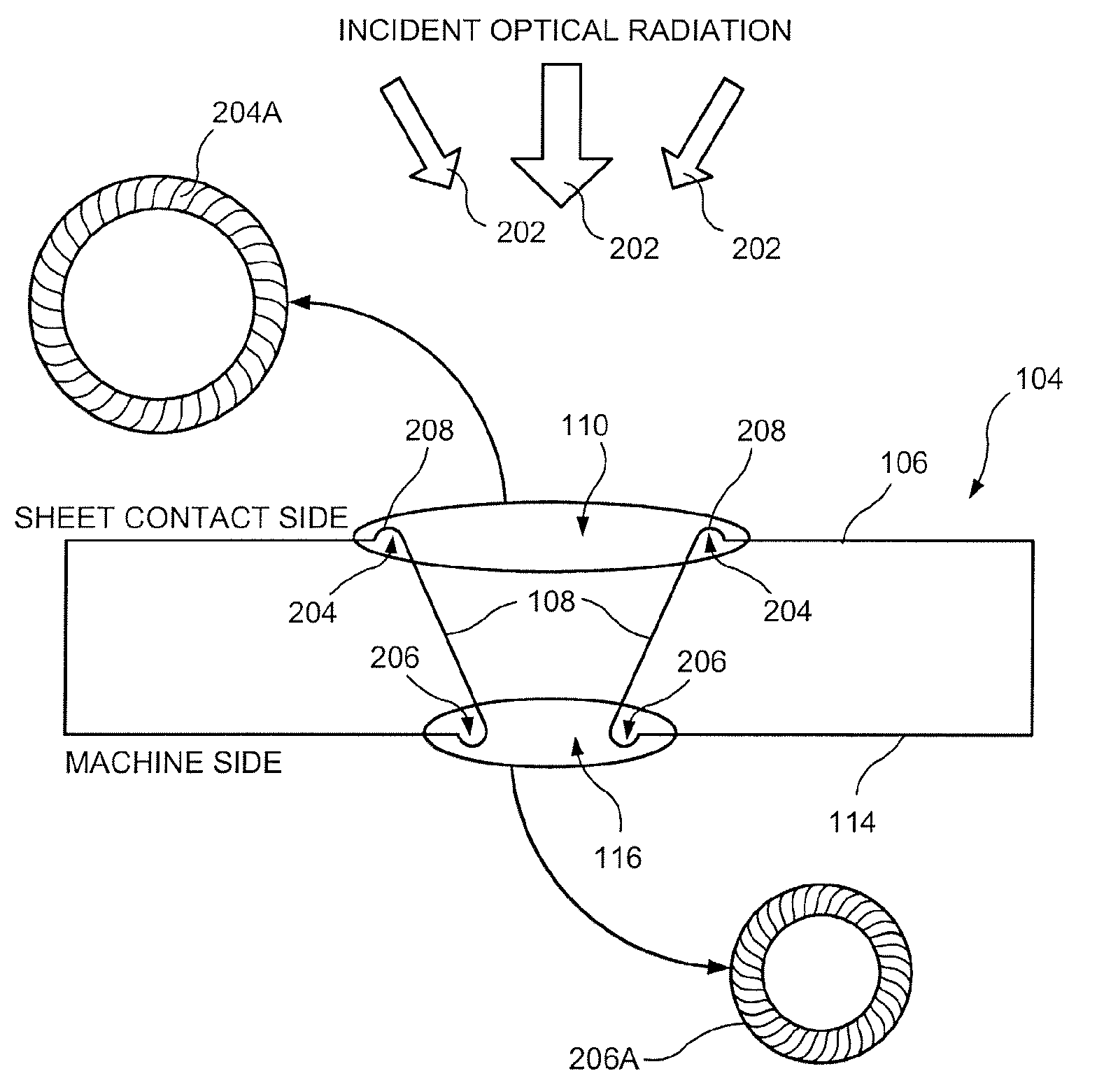
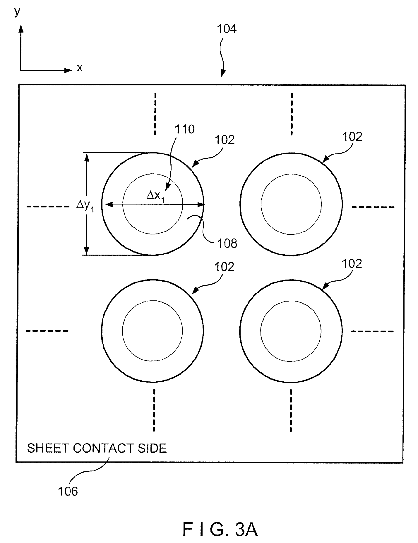
[0027]One embodiment relates to belts or sleeves for producing spunlace or hydroentangled nonwoven products. The belt or support member or sleeve is an air and / or water permeable support member which can be made from an extruded or laminated film in which defined holes are made in order to have the required air and / or water permeability. These holes can have different diameters ranging from 0.01 mm to 5 mm with different entry angles on the belt's or sleeve's surface. The shape of the holes can be round, square, oval or any specific shape such as a star shape. The holes on the surface of the support member can be randomly positioned or with specific density in some areas or uniformly on the surface depending on the required effect. Instead of holes, lines or grooves can be cut / etched into the support member or belt to create patterns, or even logos. The support member can be produced with one or more layers of a polymeric film, with or without reinforcement, which can be woven or a nonwoven. It can also be made as a laminate with a woven or nonwoven layer between two or more layers of a polymeric film. This reinforcement increases the mechanical characteristics and stability of the belt / sleeve.
[0028]The surface of the support member can be processed in order to create a topography by cutting or graving a pattern e.g. a honeycomb structure, and / or can be treated with a chemical coating for a specific application such as static dissipation, contamination / soil release, improving durability etc. The surface of the support member can be graved, for example, to create a topography for a patterning application. The support member can be made as a sleeve to be installed on a drum (sleeve) or as an endless or seamable (made endless) belt or support member. The use of this type of support member allows a better reflection of hydraulic energy when compared to a prior art standard woven belt. This improves entangling of fibers in the nonwoven and prevents fiber penetration into the support belt apertures / holes / voids, which can lead to fiber loss or difficulty in releasing the nonwoven cleanly and uniformly from the support belt / sleeve, as may be observed in woven belts or support members. The result is: better fiber entanglement and less fiber picking, resulting in better product release or transfer from this support member to another position or support member. The machine side can have an MD yarn array of monofilaments laminated or partially embedded into the support belt / sleeve in order to create higher drainage.

Problems solved by technology

These rolls are typically expensive and operate on the principle of compressing certain areas of the fibrous web to create the required patterns or marks.
However, there are several drawbacks of using a separate process for creating the pattern or mark on the nonwoven product.
Second, higher processing costs would be incurred due to a separate patterning or marking stage.
Lastly, the two-stage process would lead to a low bulk in the finished product due to high pressure compression during calendaring.
Prior art nonwoven products made with these known patterning processes do not have clear, well defined raised portions and therefore the desired patterns are difficult to see.
In addition, the raised portions of prior art embossed nonwoven products are not dimensionally stable and their raised portions lose their three-dimensional structure when stressed, as for example, when they are handled or laundered.
One of the main problems which arises during the production of nonwoven products is that of achieving the cohesion of the structure in order to give the products mechanical characteristics according to the application in question, while maintaining or imparting particular physical characteristics, such as bulk, hand, appearance, etc.

Method used


Image

  • Industrial fabric, and method of making thereof
  • Industrial fabric, and method of making thereof
  • Industrial fabric, and method of making thereof

Examples


Embodiment Construction

[0046]The instant invention will now be described more fully hereinafter with reference to the accompanying drawings, in which preferred embodiments of the invention are shown. This invention may, however, be embodied in many different forms and should not be construed as limited to the illustrated embodiments set forth herein. Rather, these illustrated embodiments are provided so that this disclosure will be thorough and complete, and will fully convey the scope of the invention to those skilled in the art.

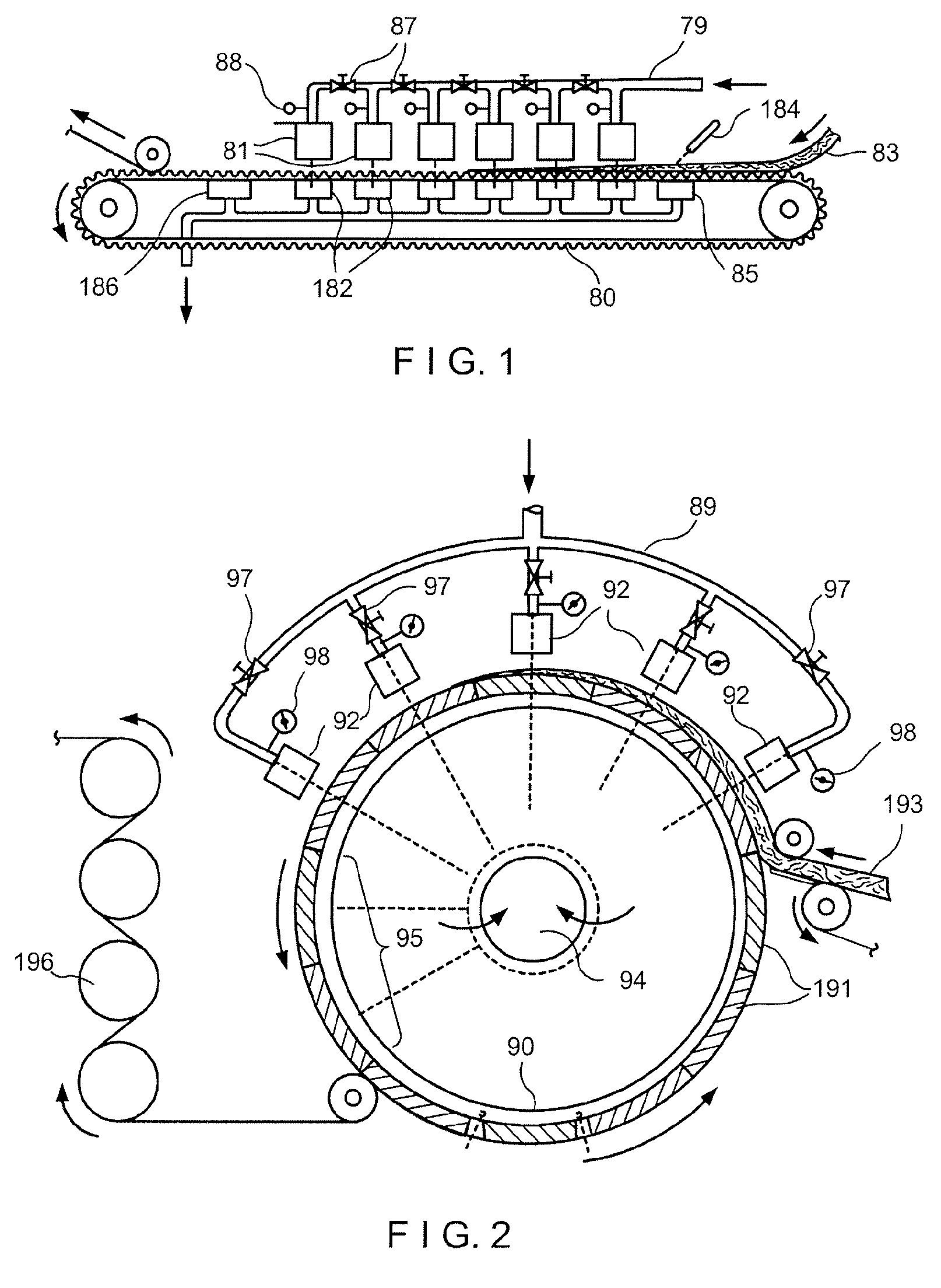
[0047]The present invention provides a continuous support member for use in the apparatus shown in FIGS. 1 and 2, for example. The nonwoven support member functions in place of a traditional woven support fabric, and aids in imparting desired texture, hand, and bulk to the nonwoven products produced thereon. The support member of the present invention may reduce the manufacturing time and costs associated with the production of nonwovens.

[0048]A belt or sleeve, as described herei...


PUM

PropertyMeasurementUnit
heightaaaaaaaaaa
diameteraaaaaaaaaa
pressuresaaaaaaaaaa

Abstract

A support member such as a belt or sleeve includes a topographical pattern on its sheet contact side. A plurality of land areas, corresponding depressions, through voids, and / or groove areas are formed on the top surface of the support member to produce the topographical pattern. The land areas, corresponding depressions, through voids, and / or groove areas may be formed by graving, cutting, etching, embossing, mechanical perforation or a combination thereof. The improved belt or sleeve imparts desired physical characteristics, such as bulk, appearance, texture, absorbency, strength, and hand to a nonwoven product produced thereon.

Description

CROSS-REFERENCE TO RELATED APPLICATION[0001]This application is a 371 of PCT / US2009 / 056007 filed on Sep. 4, 2009 published on Mar. 18, 2010 under publication number WO 2010 / 030570 A and claims priority benefits of U.S. Provisional Patent Application Ser. No. 61 / 096,149 filed Sep. 11, 2008, U.S. Provisional Patent Application Ser. No. 61 / 121,998 filed Dec. 12, 2008, U.S. Provisional Patent Application Ser. No. 61 / 147,637 filed Jan. 27, 2009, U.S. Provisional Patent Application Ser. No. 61 / 147,894 filed Jan. 28, 2009, the disclosures of which are incorporated herein by reference.BACKGROUND OF THE INVENTION[0002]1. Field of the Invention[0003]The present invention is directed to endless structures, and particularly, industrial fabrics used in the production of nonwoven products. More particularly, the instant invention is directed to support members such as belts or sleeves used in the production of patterned, marked, or textured nonwoven products.[0004]2. Description of the Prior Art[...

Claims


Application Information

Patent Timeline
Patent Type & Authority Patents(United States)
IPC IPC(8): B32B3/24B32B5/10B65H20/00B65H37/00D04H1/44D04H1/46D04H5/02
CPCD04H1/44B65H37/00B65H20/00B32B5/10D04H1/46D04H5/02B65H2301/5142B65H2406/332B65H2701/177B65H2406/3223B32B3/266B32B3/30B32B5/022B32B5/024B32B5/142B32B5/22B32B5/26B32B27/08B32B27/12B32B27/18B32B27/308B32B27/36B32B27/40B32B2255/00B32B2260/021B32B2260/046B32B2262/02B32B2262/0261B32B2262/0269B32B2262/0276B32B2307/21B32B2307/50B32B2307/514B32B2307/5825B32B2307/724B32B2307/726B32B2413/00Y10T428/24273Y10T428/24298Y10T428/24322D04H18/04
Inventor RIVIERE, PIERREMONNERIE, JEAN-LOUISKARLSSON, JONASEAGLES, DANAMOURAD, SABRIHANSEN, ROBERT A.
Owner ALBANY INT CORP
Why Eureka
Try Eureka