Lightweight, self-ballasting photovoltaic roofing assembly

a photovoltaic roof and self-balancing technology, applied in the safety of solar heat collectors, lighting and heating apparatuses, batteries, etc., can solve the problems of increasing assembly complexity, increasing manufacturing costs, and reducing the cost of solar cells, so as to facilitate the transition, reduce air pollution and global warming, and improve the cost competitiveness of photovoltaic technology

Inactive Publication Date: 2006-02-28
PLUTO ACQUISTION CO LLC +1
View PDF35 Cites 108 Cited by
  • Summary
  • Abstract
  • Description
  • Claims
  • Application Information

AI Technical Summary

Benefits of technology

[0026]h) a roofing assembly which yields social benefits by making photovoltaic technology more cost competitive. Thi

Problems solved by technology

As the cost of solar cells declines, the non-solar cell components necessary for a functioning photovoltaic system begin to dominate the overall system costs.
a) by including a roofing paver, the assembly is more complicated than necessary and more costly to manufacture.
b) the assembly does not employ a method by which to limit the temperatures experienced by the solar cells and other components. Solar cells are known to decline in efficiency with increasing temperatures. Hence, by offering no mechanism for temperature abatement, the assembly will operate less efficiently, with unknown long-term effects due to high temperature exposure.
c) by placing both a concrete paver and photovoltaic module onto the insulation block, the insulation block is inhibited from ventilating and expiring moisture. As a result, upon exposure to moisture, the insulation block takes longer to dry out, thus reducing its insulating value and degrading the integrity of the insulation block over time.
d) the assembly has multiple modes of potential failure, w

Method used


Image

  • Lightweight, self-ballasting photovoltaic roofing assembly
  • Lightweight, self-ballasting photovoltaic roofing assembly
  • Lightweight, self-ballasting photovoltaic roofing assembly

Examples


Embodiment Construction

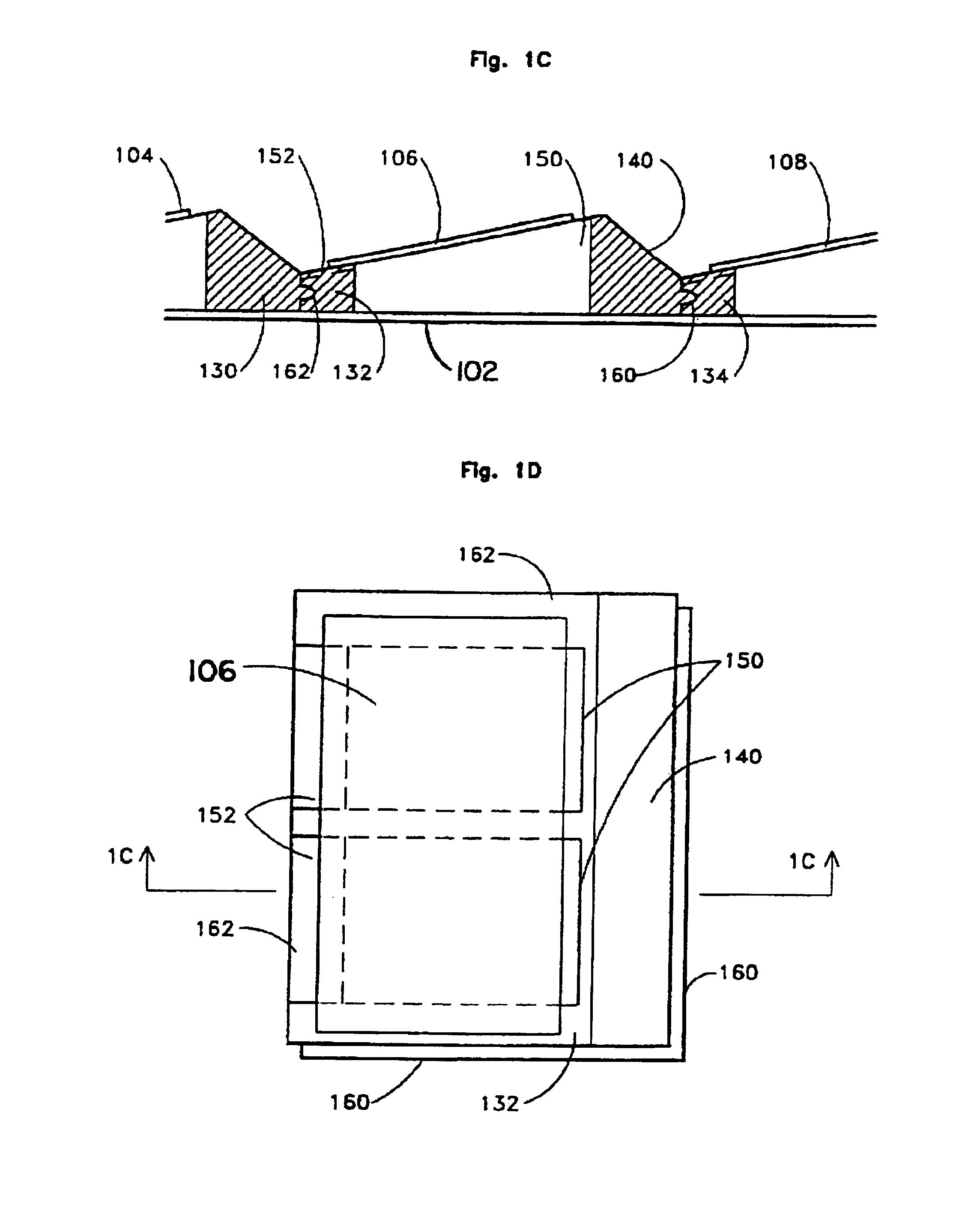
Description of FIGS. 1A-1D:

Spacer Geometry Directly on Roofing Membrane

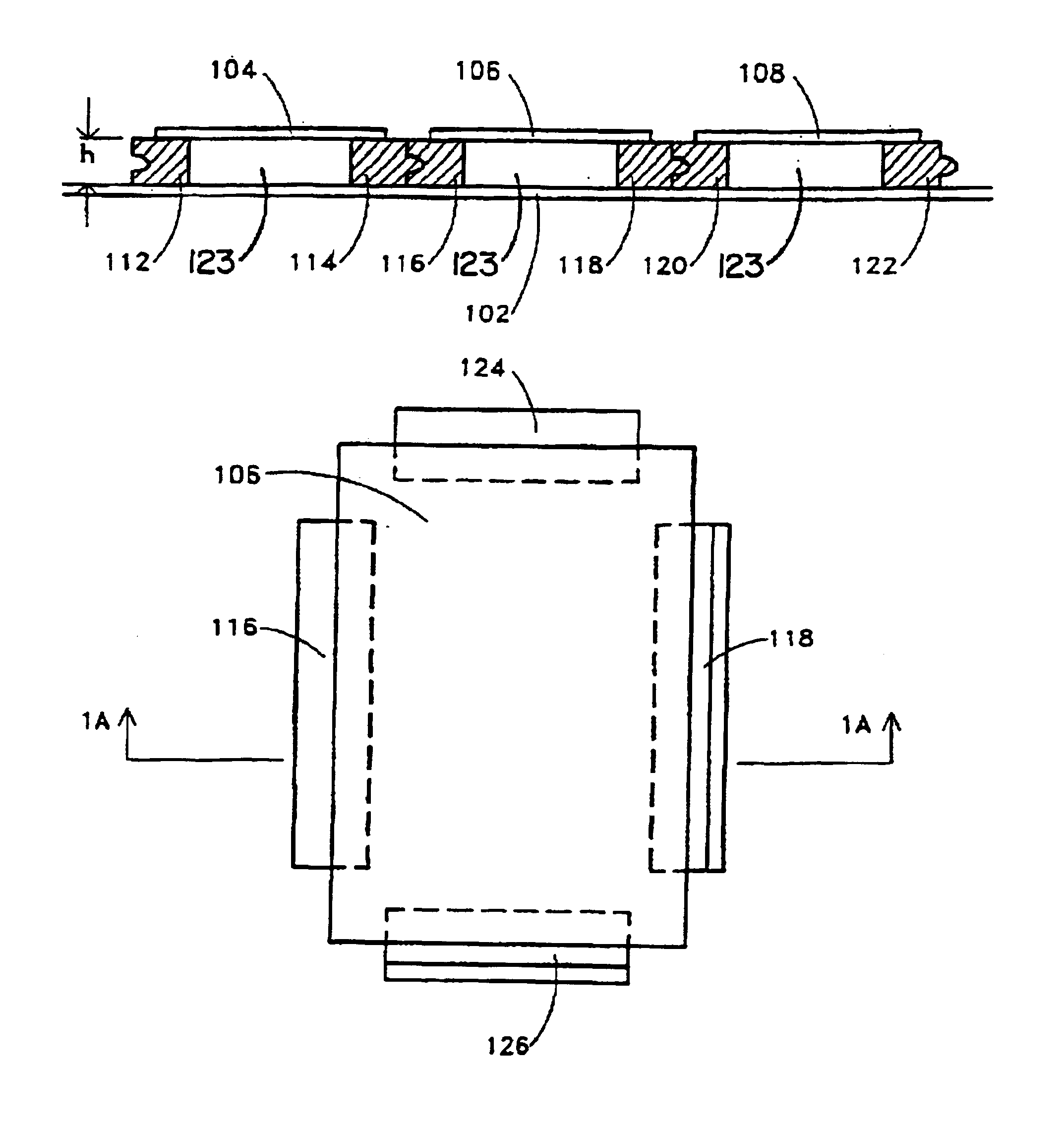
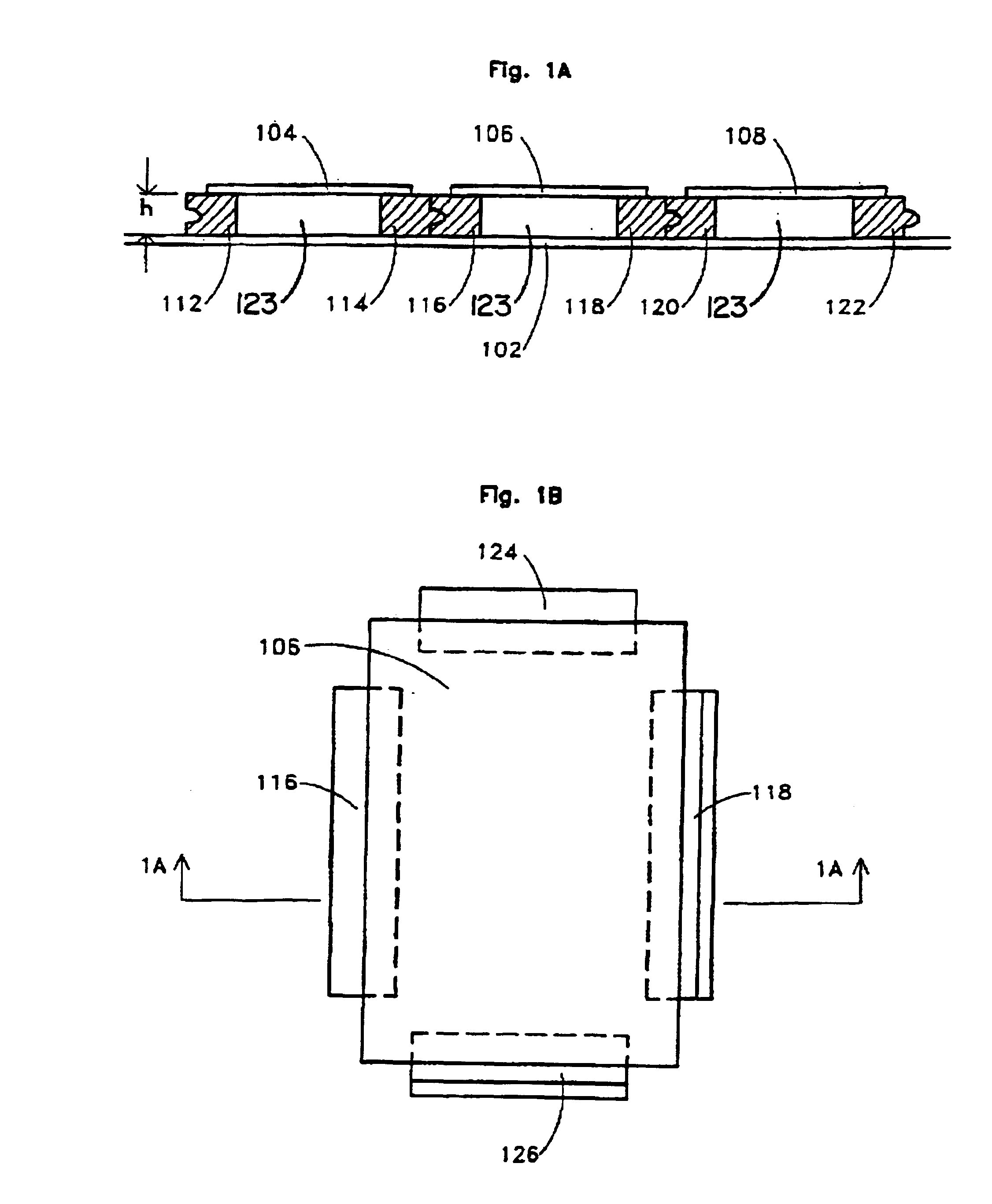
[0033]FIG. 1A shows a sectional view of a photovoltaic roofing assembly. The assembly includes a plurality of photovoltaic modules 104, 106, 108, a plurality of pre-formed spacers, pedestals, or supports 112, 114, 116, 118, 120, 122 which are respectively disposed below the plurality of photovoltaic modules 104, 106, 108 and integral therewith, or fixedly connected thereto. Spacers 112, 114, 116, 118, 120, 122 are disposed on top of a roofing membrane 102. Photovoltaic modules 104, 106, 108 and the associated spacers 112-122 define open regions 123 beneath the photovoltaic modules.

[0034]Membrane 102 is supported on conventional roof framing (not shown), and may be attached thereto by conventional methods, such as fasteners or adhesives. Membrane 102 may also rest directly on an insulation block which is supported on conventional roof framing. Modules 104, 106, 108 are electrically connected using electrical condu...


PUM


Abstract

A photovoltaic roofing assembly comprises a roofing membrane (102), a plurality of photovoltaic modules (104, 106, 108) disposed as a layer on top of the roofing membrane (102), and a plurality of pre-formed spacers, pedestals or supports (112, 114, 116, 118, 120, 122) which are respectively disposed below the plurality of photovoltaic modules (104, 106, 108) and integral therewith, or fixed thereto. Spacers (112, 114, 116, 118, 120, 122) are disposed on top of roofing membrane (102). Membrane (102) is supported on conventional roof framing, and attached thereto by conventional methods. In an alternative embodiment, the roofing assembly may have insulation block (322) below the spacers (314, 314′, 315, 315′). The geometry of the pre-formed spacers (112, 114, 116, 118, 120, 122, 314, 314′, 315, 315′) is such that wind tunnel testing has shown its maximum effectiveness in reducing net forces of wind uplift on the overall assembly. Such construction results in a simple, lightweight, self-ballasting, readily assembled roofing assembly which resists the forces of wind uplift using no roofing penetrations.

Description

[0001]This invention was made with Government support under Agreement No. FG09-95EE15638 awarded by the Department of Energy. The Government has certain rights in this invention.CROSS REFERENCE TO RELATED APPLICATIONS[0002]This application is related to U.S. Pat. No. 5,316,592, issued May 31, 1994 to Dinwoodie, and U.S. Pat. No. 5,505,788, issued Apr. 9, 1996 to Dinwoodie, the disclosures of which are incorporated by reference.BACKGROUND OF THE INVENTION[0003]This invention generally relates to a photovoltaic roofing assembly, and in particular to a lightweight photovoltaic roofing assembly requiring no roofing penetrations and which resists wind up-lift due to specialized component geometry and by acting as an integral assembly.[0004]As the cost of solar cells declines, the non-solar cell components necessary for a functioning photovoltaic system begin to dominate the overall system costs. For this reason, there is a growing trend to develop photovoltaic assemblies which eliminate ...

Claims


Application Information

Patent Timeline
IPC IPC(8): E04D13/18H01L31/048E04D13/00F24J2/52H01L31/042
CPCF24J2/5237F24J2/5239H02S20/24F24J2/4638F24J2002/467F24J2002/4692Y02B10/12Y02B10/20Y02E10/47Y10S136/291F24J2002/5292F24S40/85F24S2080/015F24S25/16F24S2025/6007F24S25/11F24S2025/02Y02E10/50Y02B10/10
Inventor DINWOODIE, THOMAS L.
Owner PLUTO ACQUISTION CO LLC
Why Eureka
Try Eureka