Nanostructured Material-Based Thermoelectric Generators

a nanostructured material and generator technology, applied in the field of power generators, can solve the problems of high thermal conductivity , poor behavior of materials, and high weight of devices made of high performace materials, and achieve high seebeck coefficient, high specific power, and high transition temperature

Inactive Publication Date: 2009-02-19
NANCOMP TECHNOLOGIES INC
View PDF98 Cites 82 Cited by
  • Summary
  • Abstract
  • Description
  • Claims
  • Application Information

AI Technical Summary

Benefits of technology

[0011]In one embodiment, the thermoelectric device includes a first member designed to collect heat from a heat source. The first member can be designed to withstand temperatures ranging from below 0° C. up to about 600° C. and above. The thermoelectric device can also include a second member in spaced relations from the first member for dissipating heat from the first member. The first and second member, in an embodiment, may be made from a thermally conductive material, such a aluminum nitride. The thermoelectric device further includes a core positioned between the first member and a second member for converting heat from the first member to useful energy. In one embodiment, the core includes a nanotube thermal element exhibiting a relatively high Seebeck coefficient that increases with an increase in temperature, and a conductive element exhibiting a relatively high transition temperature. The thermal element, in an embodiment, may have a density range of from about 0.1 g / cc to about 1.0 g / cc, which can result in weight saving over traditional materials used in a thermoelectric device. The thermal element and conductive element may be coupled to one another, so as to allow the core to operate within in a substantially high temperature range, for example up to about 600° C. and above. In addition, the core may be designed to achieve a relatively high specific power up to and exceeding about 3 W / g at a ΔT of about 400° C.
[0012]In another embodiment, a method of generating power is provided. The method includes initially providing a thermoelectric device having (i) a first member designed to collect heat from a heat source, (ii) a second member in spaced relations from the first member for dissipating heat from the first member, and (iii) a core positioned between the first member and a second member for converting heat from the first member to useful energy, the core having a nanotube thermal element exhibiting a relatively high Seebeck coefficient that increases with an increase in temperature, and a conductive element exhibiting a relatively high transition temperature, the elements coupled to one another allowing the core to operate in a substantially high temperature range. Next the thermoelectric device can be positioned so as to permit the first member to collect heat from a heat source. Thereafter, the collected heat can be driven across the core to the second member due to a temperature differential between the first member and the second member. Subsequently, during the course of heat transfer, the core is allowed to convert the heat transferred across it into power. In one embodiment, once power has been generated, the power can be directed to another to permit such a device to operate. Alternatively, if the thermoelectric device is coupled to a machine or device capable of generating waste heat, so that the waste heat can act as a heat source to be captured, the device can convert the waste heat to power and redirect the power to the machine for further use. To enhance efficiency and power generated, the number of thermal elements and conductive elements in the core can be increased. In addition, the power generated can be up to and exceeding about 3 W / g at a ΔT of about 400° C.
[0013]A method of manufacturing a thermoelectric device is also provided. The method includes initially providing at least one nanotube thermal element exhibiting a relatively high Seebeck coefficient that increases with an increase in temperature. In one embodiment, the nanotube thermal element can be provided with a density range of from about 0.1 g / cc to about 1.0 g / cc. In addition, the nanotube thermal element can be doped with one of a p-type dopant, n-type dopant, or both. Next, the thermal element can be coupled to a corresponding conductive element exhibiting a relatively high transition temperature to provide a core member. In one embodiment, the thermal element and the conductive element can withstand a temperature range of from below 0° C. up to about 600° C. and above. Thereafter, the core member may be positioned between a first member designed to collect heat from a heat source, and a second member in spaced relations from the first member for dissipating heat from the first member. To provide the thermoelectric device with the ability to increase the power generated, in one embodiment, the number of nanotube thermal elements on can be increased.

Problems solved by technology

so that materials with a high thermal conductivity λ tend to behave poorly as thermoelectric generators, because they can leak away thermal energy that otherwise can contribute to power generation.
However, for many practical considerations, weight may be important.
As such, devices made of this high performace material can be relatively heavy.
However, thermoelectric devices or systems that utilize Bi2Te3, SiGe alloys, or other similar materials can only generate a specific power at a level of from about 1-5 W / kg.
Furthermore, in many of the contemplated applications, the temperatures to which the thermoelectric devices can be exposed can be substantially high.
Unfortunately, Bi2Te3, SiGe alloys, or other similar materials used in presently available thermoelectric devices or systems tend to melt as the temperature approaches about 400° C.

Method used


Image

  • Nanostructured Material-Based Thermoelectric Generators
  • Nanostructured Material-Based Thermoelectric Generators
  • Nanostructured Material-Based Thermoelectric Generators

Examples


example i

[0074]In this example, a thermoelectric device or generator is provided using at least one carbon nanotube sheet made in accordance with an embodiment of the present invention.

[0075]With reference now to FIG. 7, there is shown a schematic diagram of an array 70 of a thermal element 71 and a conducting element 72 in substantial linear alignment. In one embodiment, element 71 can be a sheet of carbon nanotubes doped with a p-type dopant. Alternatively, element 71 can be a sheet of carbon nanotubes doped with an n-type dopant. Although reference is made to a sheet of carbon nanotubes, it should be appreciated that a plurality of sheets can be used, with each placed on top of one another. This is because, when using a plurality of sheets, the mass can increase, which can result in more power output in the thermoelectric device.

[0076]Conducting element 72, on the other hand, may be made from a metallic material, such as copper, nickel, or other similar conductive materials. In one embodi...

example ii

[0091]In this embodiment, a thermoelectric device is provided using at least one carbon nanotube yarn made in accordance with an embodiment of the present invention.

[0092]Looking now at FIG. 10, a solar collector 100 is provided. The solar collector 100, in an embodiment, includes a thermoelectric device 101 having a outer ring 102 and an inner member 103 concentrically positioned relative to the outer ring 102. Inner member 103, as illustrated, may be a hot plate designed to collect heat from solar rays, while outer ring 102 may be a cool plate designed to dissipate heat. Thermoelectric device 101 may also include a core 104 having at least one carbon nanotube yarn 105, made from a plurality of intertwined nanotubes in substantially alignment. Yarn 105, in an embodiment, extends radially between the inner member 103 and the outer ring 102, and can act as a thermal element. In one embodiment, yarn 105 may be a p-type element or n-type element coated (i.e., electroplated) along its l...

example iii

[0093]In this embodiment, a multi-element thermoelectric array is provided using a plurality of carbon nanotube yarns made in accordance with one embodiment of the present invention.

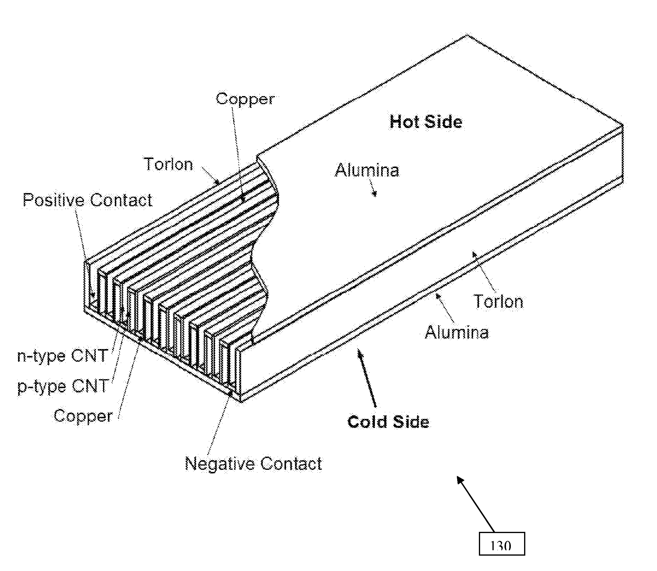
[0094]As illustrated in FIGS. 11A-D, a thin thermoelectric panel 110 is provided. The thin panel 110, in an embodiment, includes a plurality of thin thermal elements 111 (FIG. 11C) made from nanotube yarns. In one embodiment, about 30-1000 or more elements 111 having high hot-cold gap length and a small cross-section can be provided on the thin panel 110. These elements 111, designed to act as p-type elements, may be positioned on, for example, a substrate 112 made from, for example, aluminum nitride, mica or other similar material. In an embodiment, the substrate 112 may be coated with copper or nickel on a side on which the carbon nanotube thermal elements are situated (FIG. 11A), while its opposite side remains uncoated (FIG. 11B). On the uncoated side, panel 110 may be provided with a plurality of co...


PUM


Abstract

A thermoelectric device that can exhibit substantially high specific power density is provided. The device includes core having a p-type element made from carbon nanotube and an n-type element. The device also includes a heat plate in and a cool plate, between which the core can be positioned. The design of the thermoelectric device allows the device to operate at substantially high temperature and to generate substantially high power output, despite being light weight. A method for making the thermoelectric device is also provided.

Description

RELATED U.S. APPLICATIONS[0001]The present invention claims priority to U.S. Provisional Patent Application Nos. 60 / 964,678, filed Aug. 14, 2007, and 60 / 987,304, filed Nov. 12, 2007, both of which are hereby incorporated herein by reference.TECHNICAL FIELD[0002]The present invention relates to power generators, and more particularly, to electric power generators using thermoelectric effect associated with nanostructured material arrays.BACKGROUND ART[0003]Thermal electric generators are usually made from semiconductor “n” and “p” type elements arranged in series “n” to “p”, and can be attached on one side to a hot plate or heat source, and on the other side to a cold plate or heat sink. The efficiency of these generators includes fundamentally the Carnot efficiency and secondarily the device efficiency, with overall energy conversion values of less than about 10% and usually less than about 5%.[0004]These devices typically rely on semiconductor materials having, among other things, ...

Claims


Application Information

Patent Timeline
Patent Type & Authority Applications(United States)
IPC IPC(8): H01L35/28H01L35/34B60K16/00
CPCH01L35/22H01L35/32H01L35/30H10N10/855H10N10/17H10N10/13
Inventor LASHMORE, DAVID S.WHITE, MEGHANNWHITE, BRIANDEGTIAROV, DAVIDMANN, JENNIFER
Owner NANCOMP TECHNOLOGIES INC
Why Eureka
Try Eureka