Cooling system for a tip of a turbine blade

a cooling system and turbine blade technology, applied in the field of hollow turbine blades, can solve the problems of reducing the useful life affecting the and the likelihood of failure, so as to reduce the manufacturing cost, the overall cooling effect of the turbine blade tip is higher, and the heat transfer convection coefficient of the cooling fluid is higher

Inactive Publication Date: 2005-07-12
SIEMENS ENERGY INC
View PDF23 Cites 75 Cited by
  • Summary
  • Abstract
  • Description
  • Claims
  • Application Information

AI Technical Summary

Benefits of technology

[0009]An advantage of this invention is that by forming cooling orifices using a tip cap, the necessities of welding core print out holes and drilling cooling orifices are eliminated, thereby reducing manufacturing costs.
[0010]Another advantage of this invention is that each metering slot may be sized individually to create a more efficient tip cooling system based upon supply and discharge pressures of the cooling fluids.
[0011]Yet another advantage of this invention is that the vortex chambers and other components of the cooling system result in a higher overall blade tip cooling effectiveness of a turbine blade as compared with conventional designs at least because the vortex chambers result in a higher heat transfer convection coefficient of the cooling fluids.
[0012]Still another advantage of this invention is that the film cooling holes may be placed in close proximity to the squealer tip, which enables the temperature of the tip to be reduced.
[0013]Yet another advantage of this invention is that the blade leakage flow past the end of the turbine blade may be reduced, in part, because the film cooling holes inject cooling air at much closer distances to the blade tip gap than convention designs.

Problems solved by technology

In addition, turbine blades often contain cooling systems for prolonging the life of the blades and reducing the likelihood of failure as a result of excessive temperatures.
However, centrifugal forces and air flow at boundary layers often prevent some areas of the turbine blade from being adequately cooled, which results in the formation of localized hot spots.
Localized hot spots, depending on their location, can reduce the useful life of a turbine blade and can damage a turbine blade to an extent necessitating replacement of the blade.
The process of welding the core print out holes closed and drilling holes into the blade tips is time consuming and thus, costly.
The direction and velocity of the fluid flowing through the cooling holes cannot be regulated.

Method used


Image

  • Cooling system for a tip of a turbine blade
  • Cooling system for a tip of a turbine blade
  • Cooling system for a tip of a turbine blade

Examples


Embodiment Construction

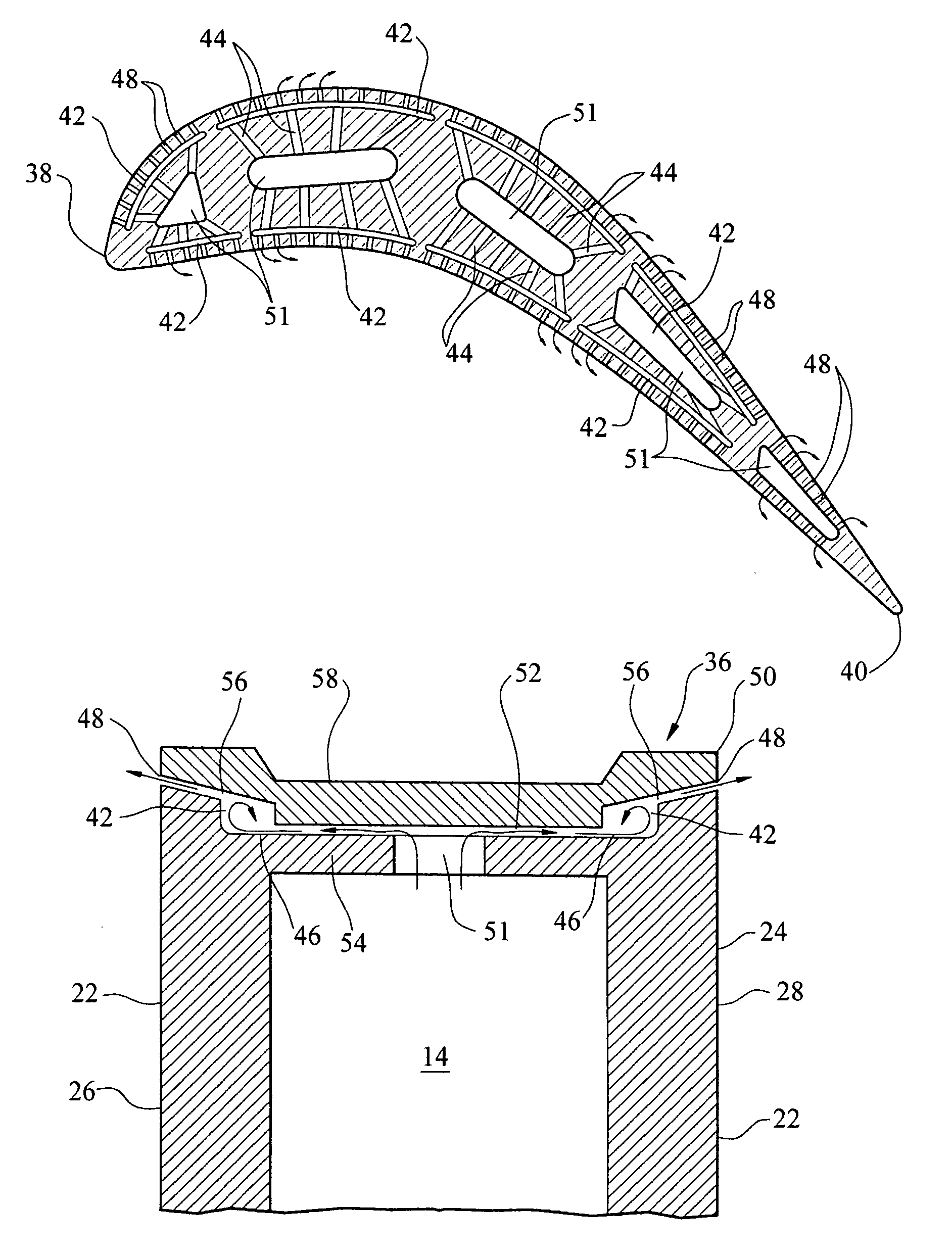
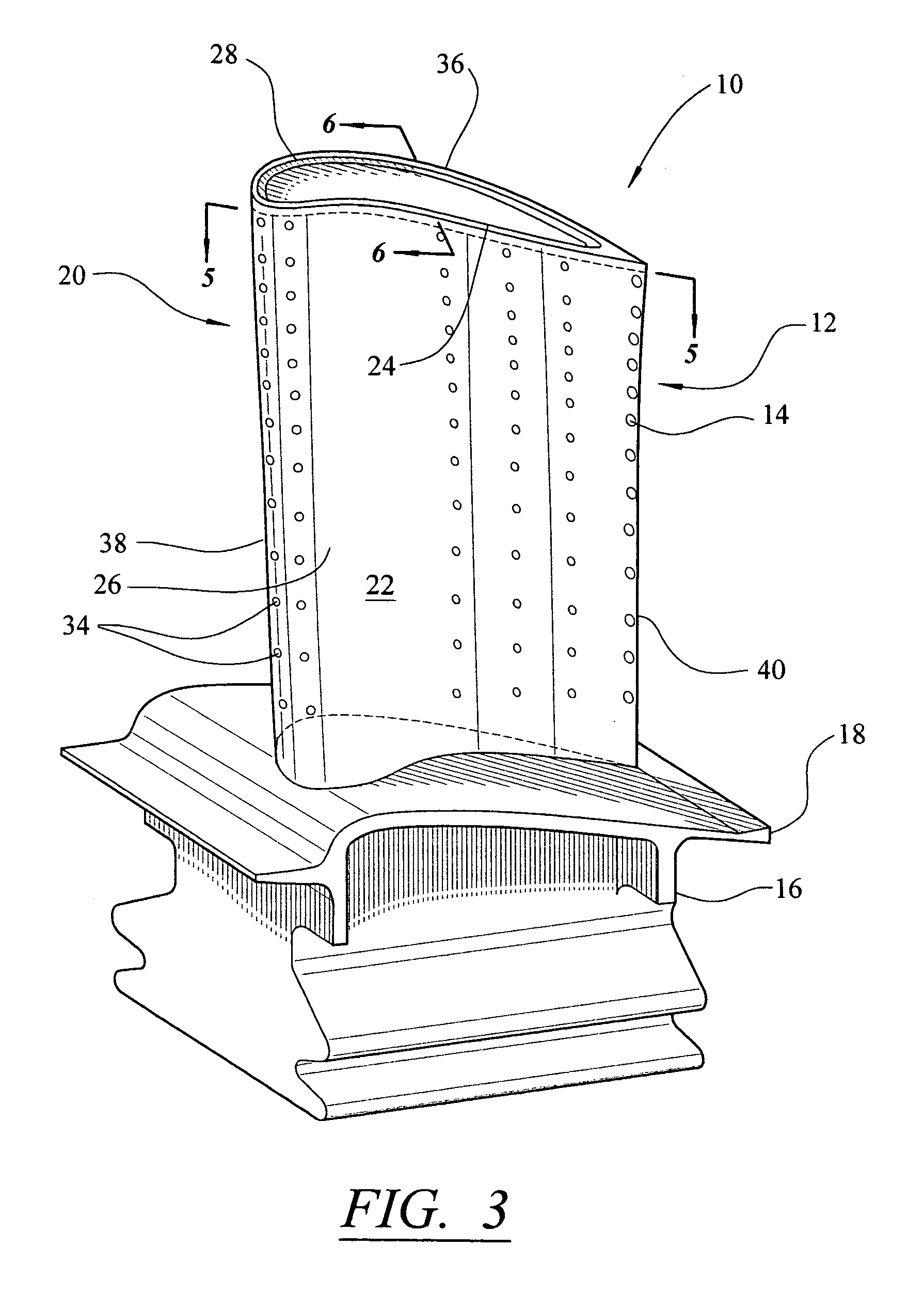
[0022]As shown in FIGS. 3–6, this invention is directed to a turbine blade cooling system 10 for turbine blades 12 used in turbine engines. In particular, turbine blade cooling system 10 is directed to a cooling system 10 located in a cavity 14, as shown in FIG. 6, positioned between outer walls 22 forming a housing 24 of the turbine blade 12. As shown in FIG. 3, the turbine blade 12 may be formed from a root 16 having a platform 18 and a generally elongated blade 20 coupled to the root 16 at the platform 18. Blade 20 may have an outer wall 22 adapted for use, for example, in a first stage of an axial flow turbine engine. Outer wall 22 may have a generally concave shaped portion forming pressure side 26 and may have a generally convex shaped portion forming suction side 28.

[0023]The cavity 14, as shown in FIG. 5, may be positioned in inner aspects of the blade 20 for directing one or more gases, which may include air received from a compressor (not shown), through the blade 20 and o...


PUM


Abstract

A turbine blade for a turbine engine having a cooling system in at least the tip portion of the turbine blade. The cooling system includes one or more vortex chambers in a tip section of the blade. The vortex chambers receive cooling fluids from metering slots that provide a pathway between internal cooling cavities of the blade and the vortex chambers. The cooling fluids may be exhausted through one or more film cooling holes. The vortex chambers, metering slots, and film cooling holes may include a tip cap attached to the tip section of the blade. At least a portion of the vortex chambers, metering slots, and film cooling holes may be formed from impressions in the tip cap or the turbine blade, or both.

Description

FIELD OF THE INVENTION[0001]This invention is directed generally to turbine blades, and more particularly to hollow turbine blades having internal cooling channels for passing gases, such as air, to cool the blades.BACKGROUND[0002]Typically, gas turbine engines include a compressor for compressing air, a combustor for mixing the compressed air with fuel and igniting the mixture, and a turbine blade assembly for producing power. Combustors often operate at high temperatures that may exceed 2,500 degrees Fahrenheit. Typical turbine combustor configurations expose turbine blade assemblies to these high temperatures. As a result, turbine blades must be made of materials capable of withstanding such high temperatures. In addition, turbine blades often contain cooling systems for prolonging the life of the blades and reducing the likelihood of failure as a result of excessive temperatures.[0003]Typically, turbine blades are formed from a root portion at one end and an elongated portion fo...

Claims


Application Information

Patent Timeline
Patent Type & Authority Patents(United States)
IPC IPC(8): B63H1/14B63H1/00F01D5/18F01D5/20
CPCF01D5/186F01D5/20
Inventor LIANG, GEORGE
Owner SIEMENS ENERGY INC
Why Eureka
Try Eureka