Liquid cold plate heat exchanger

a technology of liquid cold plate and heat exchanger, which is applied in the direction of lighting and heating apparatus, semiconductor/solid-state device details, laminated elements, etc., can solve the problems of low pressure drop and limit the heat transfer effectiveness of cold plate, and achieve the effect of reducing the net flow rate of fluid

Inactive Publication Date: 2006-05-11
AAVID THERMALLOY LLV
View PDF17 Cites 75 Cited by
  • Summary
  • Abstract
  • Description
  • Claims
  • Application Information

AI Technical Summary

Benefits of technology

[0016] surfaces with non-uniform heat fluxes can be managed at a lower net flow rat...

Problems solved by technology

The fluid flow rate has to be kept high to minimize the fluid preheat compared to the temperature difference between the cooled surface and the fluid, which by design limits the heat transfer effectiveness of the cold plate.
The normal flow concept reduces the distance that the fluid travels within the narrow fluid...

Method used


Image

  • Liquid cold plate heat exchanger
  • Liquid cold plate heat exchanger
  • Liquid cold plate heat exchanger

Examples


first embodiment

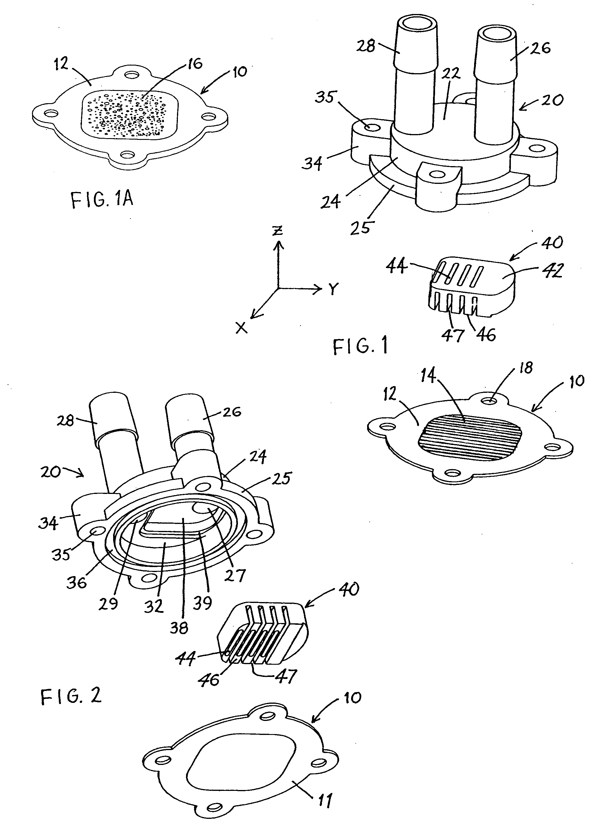
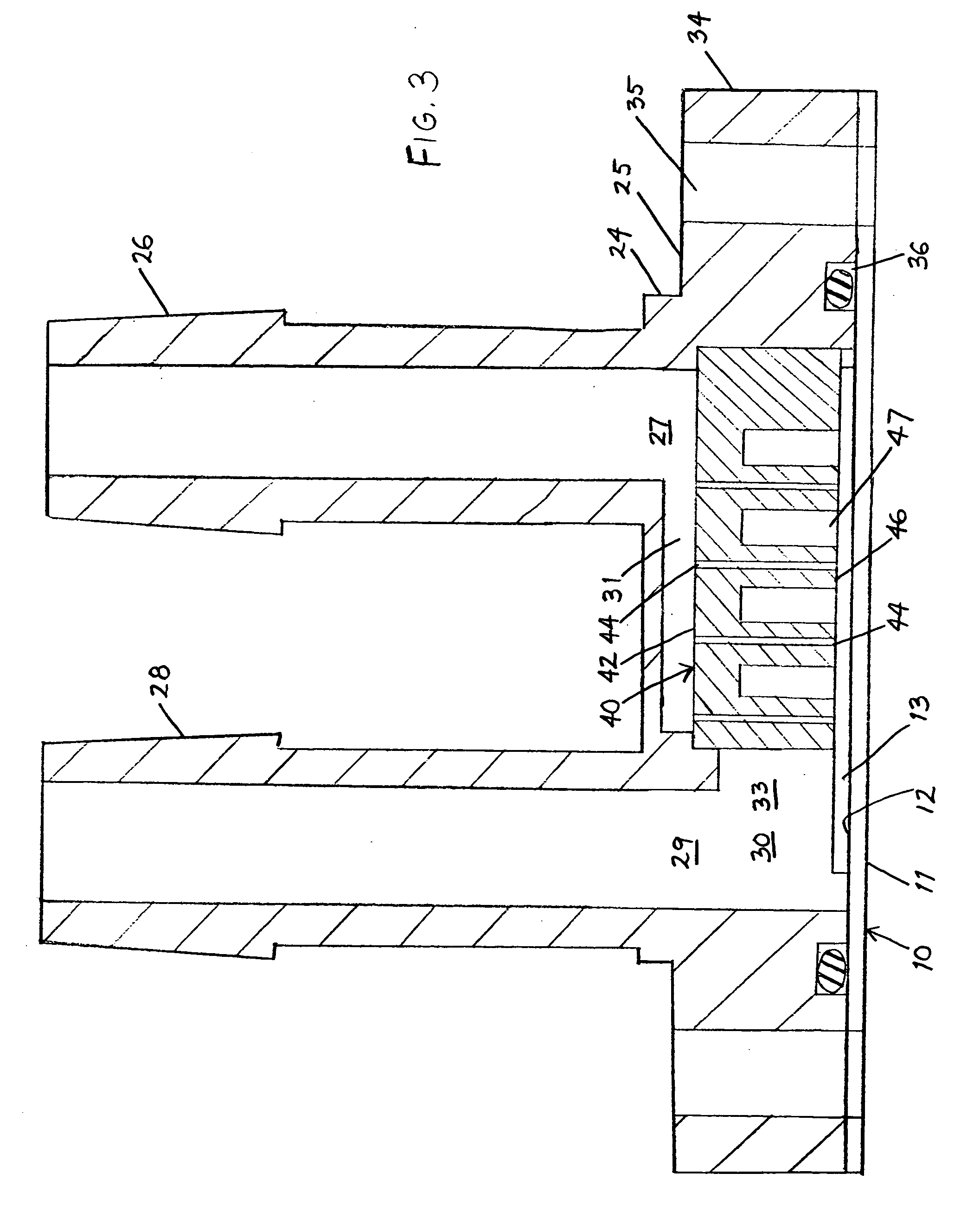
[0028] Referring to FIGS. 1 and 2, the heat exchanger according to the invention includes a metal cooling plate 10 having a heat collection surface 11 for mounting against an object to be cooled, such as a semiconductor component, and an opposed heat transfer surface 12 against which fluid is circulated to remove heat. The heat transfer surface 12 is provided with an array of parallel microfins 14 upstanding from the surface 12. These fins may be formed by rolling grooves into the plate 10 and thus may have a height of as little as 0.001 in. or less. According to an alternative embodiment, shown in FIG. 1A, the heat transfer surface is provided with a random surface enhancement in the form of a porous foam pad 16. A cover 20, which is fitted over the cooling plate 10, has a top 22 provided with an inlet nipple 26 and an outlet nipple 28 for connecting fluid conduits to circulating means such as a pump, and is surrounded by a circumferential wall 24 and a mounting base 25. The base 2...

second embodiment

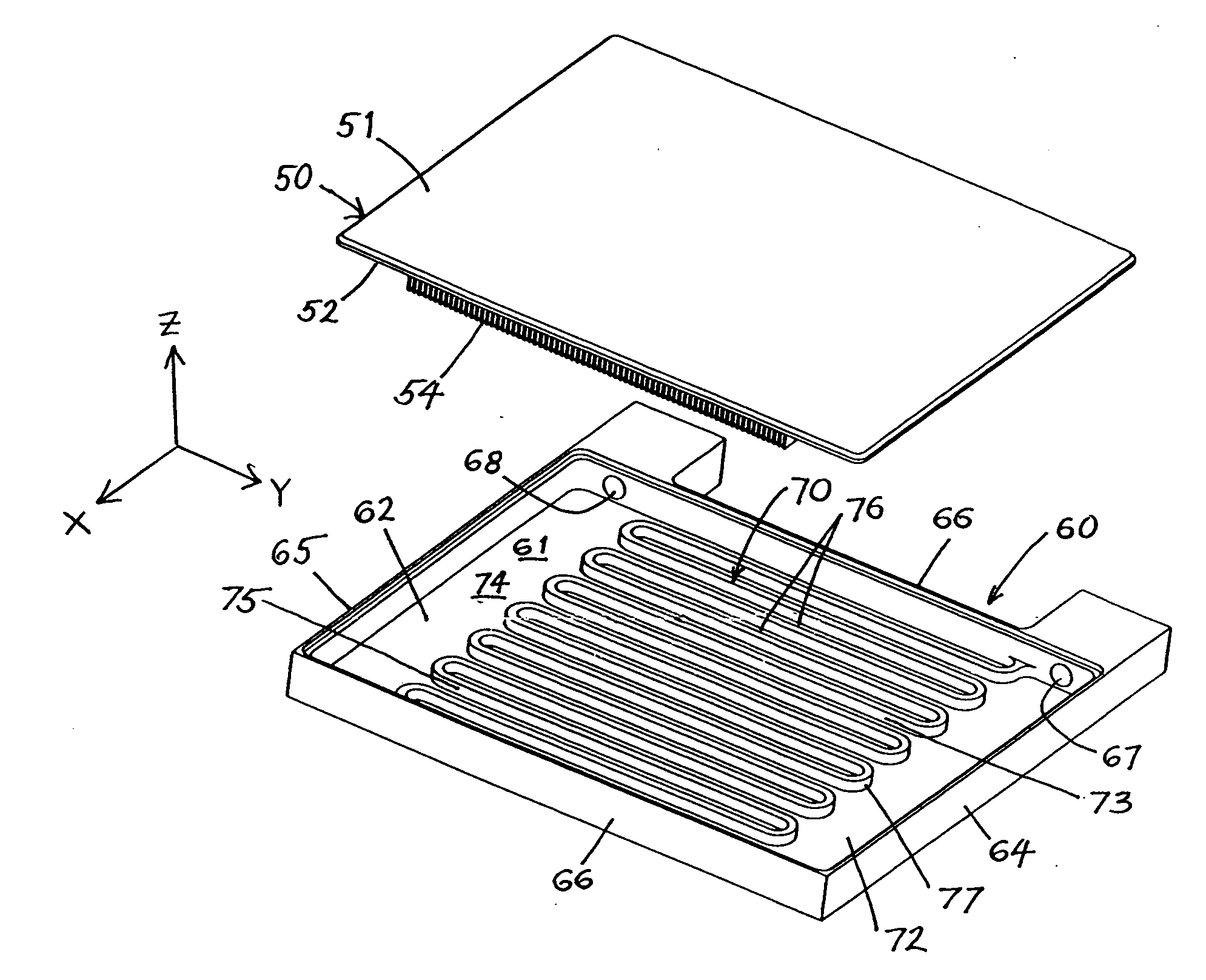
[0031] heat exchanger according to the invention is shown in FIGS. 4 and 5. The cooling plate 50 has a heat collection surface 51, a heat transfer surface 52, and microfins 54 on the heat transfer surface. The cover 60 has a base 62, as well as a front wall 64, a rear wall 65, and opposed sidewalls 66 upstanding from the edges of the base. The cover 60 is fitted to the cooling plate 50 to form a cooling chamber 61, and may be fixed by brazing (where both components are metal), adhesive bonding, or mechanical fixing with a gasket.

[0032] The flow distributor is formed by a serpentine wall 70 fixed to the base 62 and extending between the sidewalls 66, thereby dividing the cooling chamber 61 into an inlet section 72 supplied by inlet port 67 and an outlet section 74 which supplies outlet port 68. The serpentine wall 70 forms inlet channels 73 in the inlet section 72, and outlet channels 75 in the outlet section 74, wherein the inlet channels 73 alternate with the outlet channels 75. Th...


PUM


Abstract

A heat exchanger includes a cooling plate having a heat collection surface for fixing against an object to be cooled, an opposed heat transfer surface which may be provided with fins, and a cooling chamber over the heat transfer surface, the cooling chamber having an inlet port and an outlet port for circulating a fluid through the cooling chamber via a flow path between the ports. A flow distributor in the flow path forms a plurality of inlet channels communicating with the inlet port, a plurality of outlet channels alternating with the inlet channels and communicating with the outlet port, and a plurality of flow surfaces which are spaced from the heat transfer surface by gaps. The inlet channels communicate with the gaps so that a fluid entering the inlet channels via the inlet port will flow through the gaps, into the outlet channels, and out of the chamber via the outlet port. The gaps are dimensioned to increase fluid velocity and promote mixing of the fluid, thereby improving heat transfer.

Description

PRIORITY CLAIM [0001] This application claims priority under 35 USC §119 (e) from U.S. provisional application No. 60 / 625,539 filed Nov. 5, 2004.BACKGROUND OF THE INVENTION [0002] 1. Field of the Invention [0003] The invention relates to a heat exchanger of the type including a cooling plate having a heat transfer surface and an opposed heat collection surface for fixing against an object to be cooled, and further including a cooling chamber over the heat transfer surface, the cooling chamber having an inlet port and an outlet port for circulating a fluid through the cooling chamber via a flow path between the ports. [0004] 2. Description of the Related Art [0005] In conventional liquid cold plate type heat exchangers a fluid is delivered at one end of flow channels and collected at the other end. The fluid typically flows parallel to the surface to be cooled. The channels are laid out in series and parallel paths to manage the fluid path over the cooled surface as a function of flu...

Claims


Application Information

Patent Timeline
IPC IPC(8): H05K7/20
CPCF28F3/022F28F3/12F28F9/028F28F13/06H01L23/473H01L2924/0002H01L2924/00
Inventor KANG, SUKHVINDERCENNAMO, JOHN
Owner AAVID THERMALLOY LLV
Why Eureka
Try Eureka