
Hand-held high velocity air blower

a high-speed air blower and hand-held technology, applied in the field of hand-held high-speed air blowers, can solve the problems of no hand-held, battery-operated air blower capable of delivering air flow at a velocity in excess of 30 mph for an extended time period at a noise level of 90 db, and achieve the effects of reducing drag, reducing air velocity, and balancing air flow

Inactive Publication Date: 2010-11-30
WD 40 CO
View PDF16 Cites 65 Cited by
  • Summary
  • Abstract
  • Description
  • Claims
  • Application Information

AI Technical Summary

Benefits of technology

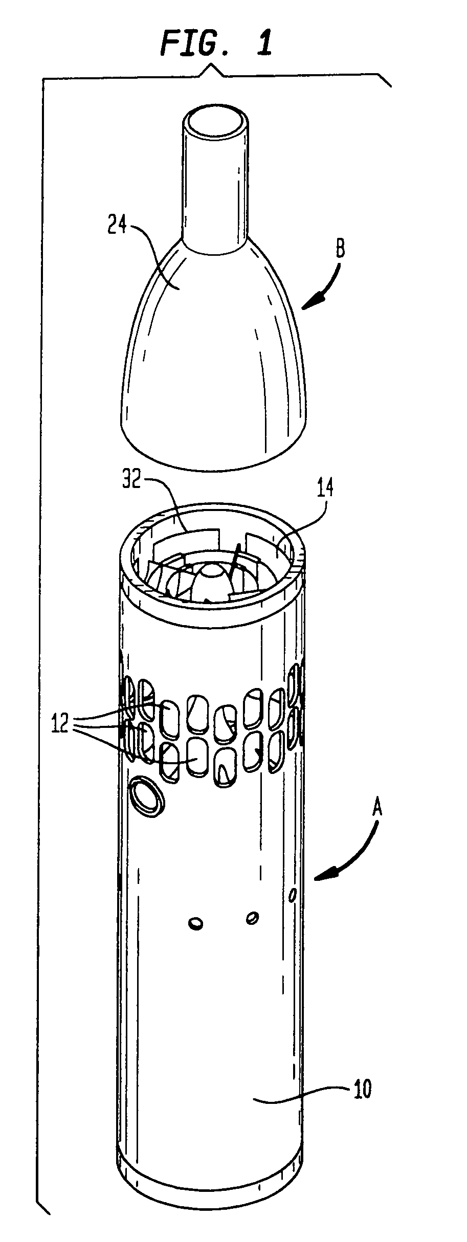
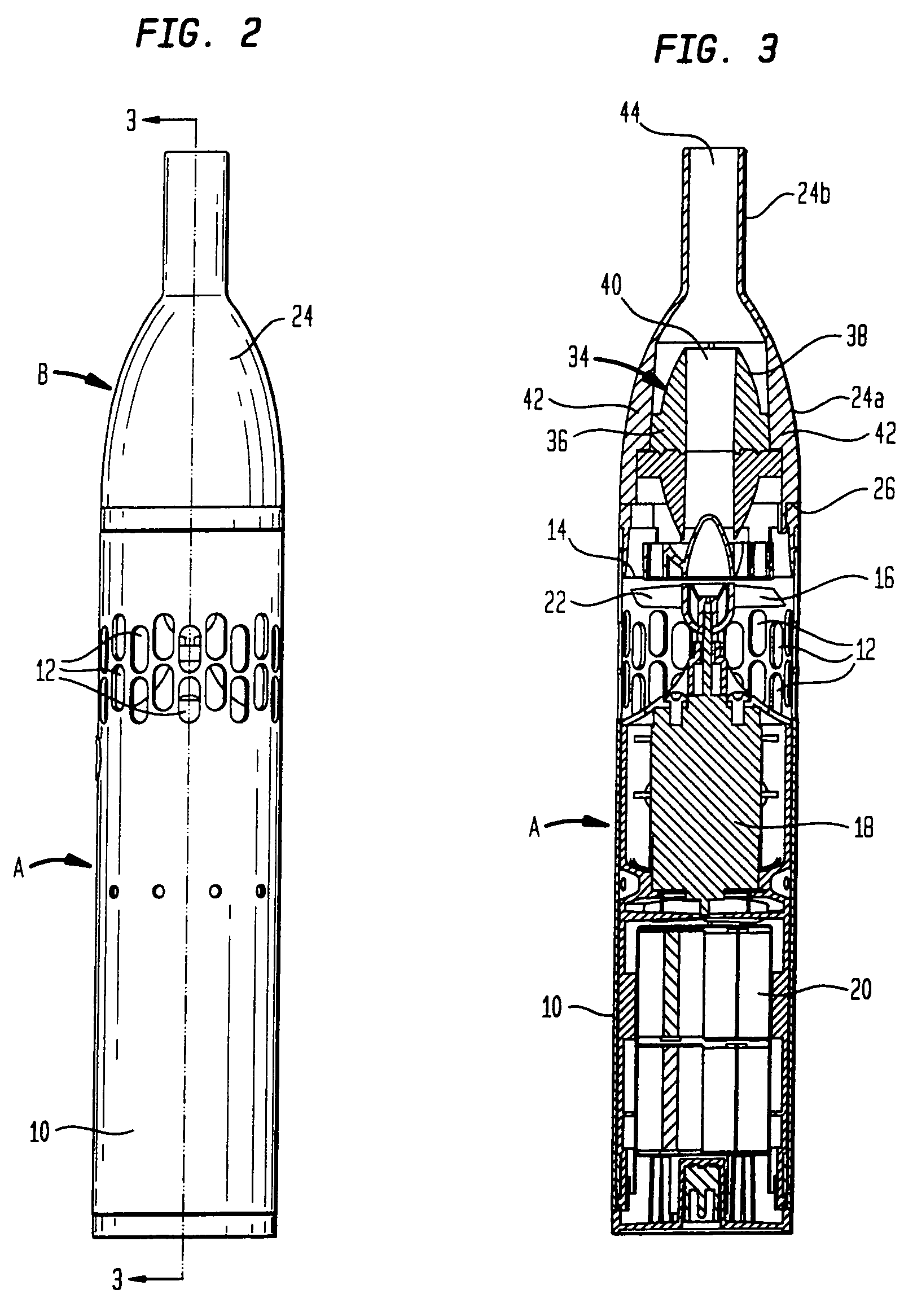
[0007]A number of key components and assemblies are needed to achieve the desired air speed and run time. One of those components is a funnel shaped air concentrator attachment detachably mounted to the front of the blower housing. The concentrator has a hollow shell with relatively larger diameter intake section and a relatively smaller diameter outlet section. The attachment is designed to focus the air exiting the relatively large diameter front opening of the housing into a small area defined by the outlet opening of the concentrator shell without reducing the air velocity. The air outlet opening of the concentrator shell is preferably about one quarter of the size of the air intake opening. The concentrator is designed to reduce drag, as well.
[0019]It is another object of the present invention to provide a hand-held high velocity air blower wherein the concentrator attachment includes a member capable of achieving balanced air flow, without creating back pressure.

Problems solved by technology

Although many types of air blowers designed for a variety of different applications are known in the art, there is no hand-held, battery operated air blower capable of delivering air flow at a velocity in excess of 30 mph for an extended time period at a noise level of 90 dB or less.

Method used


Image

  • Hand-held high velocity air blower
  • Hand-held high velocity air blower
  • Hand-held high velocity air blower

Examples


Embodiment Construction

[0038]As illustrated in the drawings, the blower of the present invention, generally designated A, is a precision engineered device that provides a high velocity of air in focused area. It is ideal for cleaning surfaces at a speed in excess of 30 mph for 10 minutes at acceptable acoustic noise levels of 90 dB. Blower A is designed for use with a detachable concentrator attachment, generally designated B, as is illustrated in FIGS. 1 and 2.

[0039]Blower A has a generally cylindrical housing 10, preferably made of aluminum. Air is drawn into the housing interior by a plurality of air intake slots 12 arranged as depicted in the drawings and is propelled out of the front end 14 of the blower using a specially designed impeller 16 within housing 10 to maximize the air velocity. The impeller 16 is powered by a motor 18 which is powered by a battery pack 20. Aside from concentrator B, the blower comes with attachments to aid in cleaning, such as a brush and nozzle.

[0040]The desired air spee...


PUM


Abstract

The hand-held air blower has a hollow, substantially cylindrical housing with an open front end, a plurality of air intake openings, an impeller situated within the housing proximate the intake openings, a motor for driving the impeller, and battery means for powering the motor. A concentrator attachment is designed for use with the blower. The concentrator has means for removably attaching the concentrator to the open front end of the blower housing and a hollow shell. The shell includes an intake section with a diameter substantially equal to the diameter of the front end of the housing and an outlet section with an outlet opening substantially smaller than the diameter of the front end of the housing. A truncated football-like shaped balancing member is provided. The balancing member has a central air flow channel. Radially directed elements mount the balancing member within the intake shell section with the balancing member spaced from the interior surface of the intake shell section so as to permit air flow therebetween.

Description

BACKGROUND OF THE INVENTION[0001]1. Field of the Invention[0002]The present invention relates to air blowers, and more particularly, to a precision engineered hand-held device that provides a flow of high velocity air focused in a limited area for cleaning surfaces or the like.[0003]2. Description of Prior Art Including Information Disclosed Under 37 CFR 1.97 and 1.98[0004]Although many types of air blowers designed for a variety of different applications are known in the art, there is no hand-held, battery operated air blower capable of delivering air flow at a velocity in excess of 30 mph for an extended time period at a noise level of 90 dB or less. Such an air blower is ideal for cleaning surfaces, electric components, computer keyboards and similar objects.BRIEF SUMMARY OF THE INVENTION[0005]The present invention is a hand-held blower designed to provide a high velocity of air in focused area at a speed in excess of 30 mph for 10 minutes at acceptable acoustic noise levels of 9...

Claims


Application Information

Patent Timeline
Patent Type & Authority Patents(United States)
IPC IPC(8): A47L5/24
CPCA47L5/14A47L5/24A47L9/00A47L9/22A47L25/00B08B5/02F04D25/084F04D25/0673
Inventor SHAANAN, GADCHEONG, PIUS YUNG-TUCK
Owner WD 40 CO
Learn More