Rotocraft power-generation, control apparatus and method

a technology of control apparatus and rotorcraft, which is applied in the direction of toy aircraft, machines/engines, transportation and packaging, etc., can solve the problems of large system development at substantial cost, difficult and expensive development of wind energy, and at best unpredictable wind energy, so as to reduce the rotational speed of the blade, increase the drag and lift, and reduce the effect of drag and li

Inactive Publication Date: 2010-12-09
CALVERLEY GRANT
View PDF20 Cites 73 Cited by
  • Summary
  • Abstract
  • Description
  • Claims
  • Application Information

AI Technical Summary

Benefits of technology

[0013]In certain embodiments, the rotorcraft may be connected directly to a generator or generating mechanism that flies with the rotorcraft blade at flight altitude. Nevertheless, in other embodiments contemplated, the force of lift pulling a tether may generate power. The blades or the rotor blades of the rotorcraft may fly upward through the air having a bare minimum of frame, fuselage, or the like. Thus, the rotorcraft may be so light that its stall speed is easily met even in the slightest wind. In this embodiment, the tether itself may be connected to a mechanical linkage capable of converting the lift energy transferred through the tether to the ground station.
[0019]Meanwhile, the blade angle of attack is distinguishable from the rotary wing angle of attack. Thus, the wing angle of attack or the rotor disk path angle with respect to the wind, may also be controlled in order to control drag, lift, and the like. In certain embodiments, such as when using a delta type of connection, the blade angle of attack and the relative rotational speed of the blade may actually be coupled. Coupling may provide more drag and lift as the rotational speed of a blade reduces, and decrease drag and lift as the relative speed increases, in order to stabilize the system. It may help to reduce drag particularly when the wind speed is comparatively higher. It may increase the lift, at the expense of increased drag, whenever the rotary blades are rotating at a comparatively slower speed, typically due to decreased local wind velocity or startup condition.
[0020]The wind velocity with respect to he earth is much more stable above the nap of the earth. At the level of building, hills, trees, and the like, wind velocities are decreased substantially by obstructions. Even in the presence of mountains, wind velocities are altered, and directions are substantially altered due to obstruction. However, it is possible to fly an autogyro on a tether at an altitude above the tops of the mountains. At a minimum, autogyro aircraft can be flown sufficiently above the nap of the local terrain features to obtain substantially constant wind.

Problems solved by technology

Thus, large systems have been developed at substantial cost to elevate wind turbine blades, propellers, or the like above the surface of the earth in areas of high wind, constant wind, or otherwise commercially feasible locations of wind energy available for harvest.
Nevertheless, wind energy has been difficult and expensive to develop.
Wind energy is at best unpredictable.
Nevertheless, the physical structures available, and the methods of installing them, are limited by the physics and engineering available to exploit them.

Method used


Image

  • Rotocraft power-generation, control apparatus and method
  • Rotocraft power-generation, control apparatus and method
  • Rotocraft power-generation, control apparatus and method

Examples


Embodiment Construction

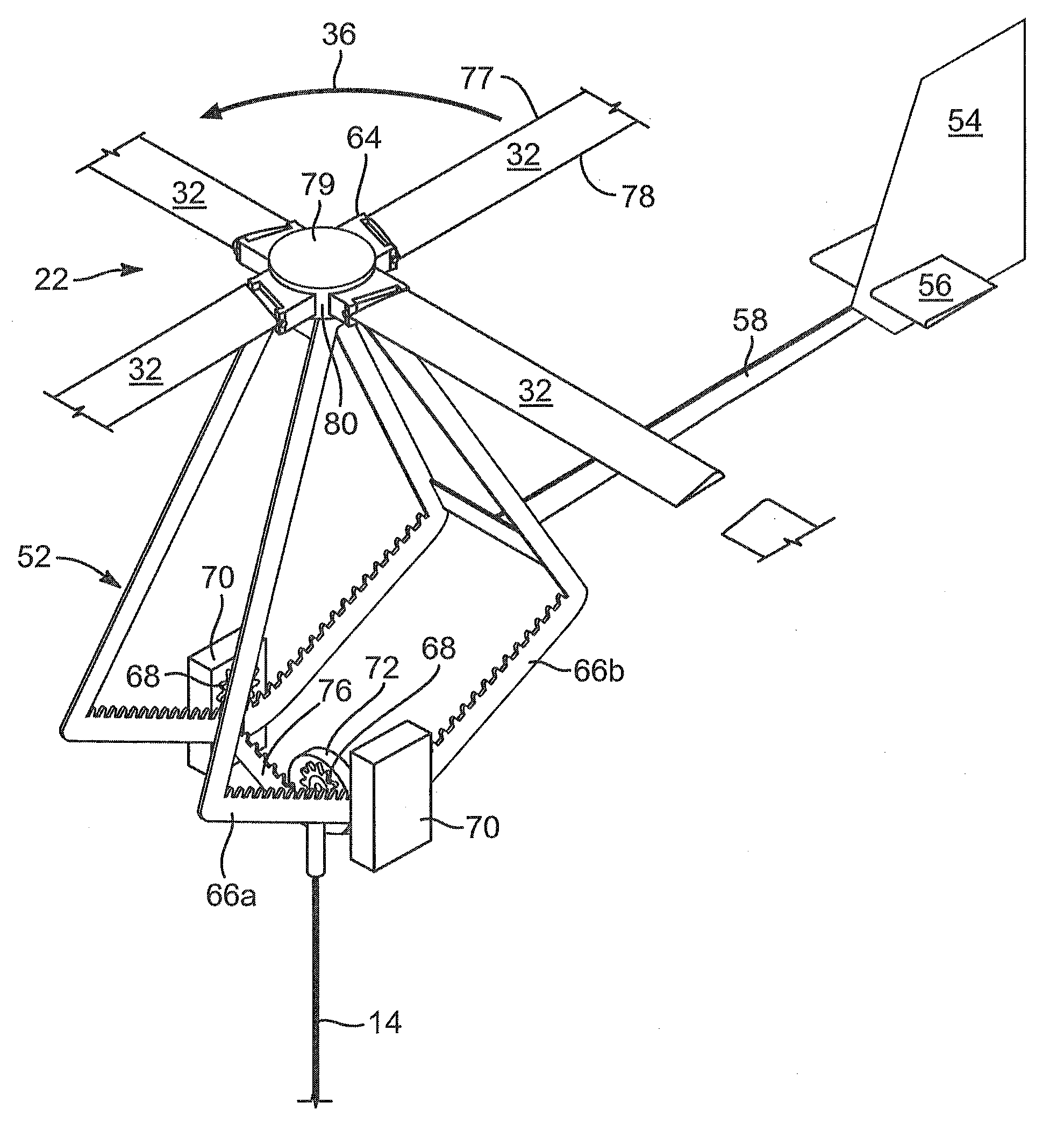
[0047]It will be readily understood that the components of the present invention, as generally described and illustrated in the drawings herein, could be arranged and designed in a wide variety of different configurations. Thus, the following more detailed description of the embodiments of the system and method of the present invention, as represented in the drawings, is not intended to limit the scope of the invention, as claimed, but is merely representative of various embodiments of the invention. The illustrated embodiments of the invention will be best understood by reference to the drawings, wherein like parts are designated by like numerals throughout.

[0048]Autogyro aircraft are described in considerable detail in U.S. Pat. No. 5,301,900 to Groen et al., which patent is incorporated herein by reference. Likewise, numerous patents to de la Cierva, Pitcairn, Barltrop and others are available in the records of the United States Patent and Trademark Office.

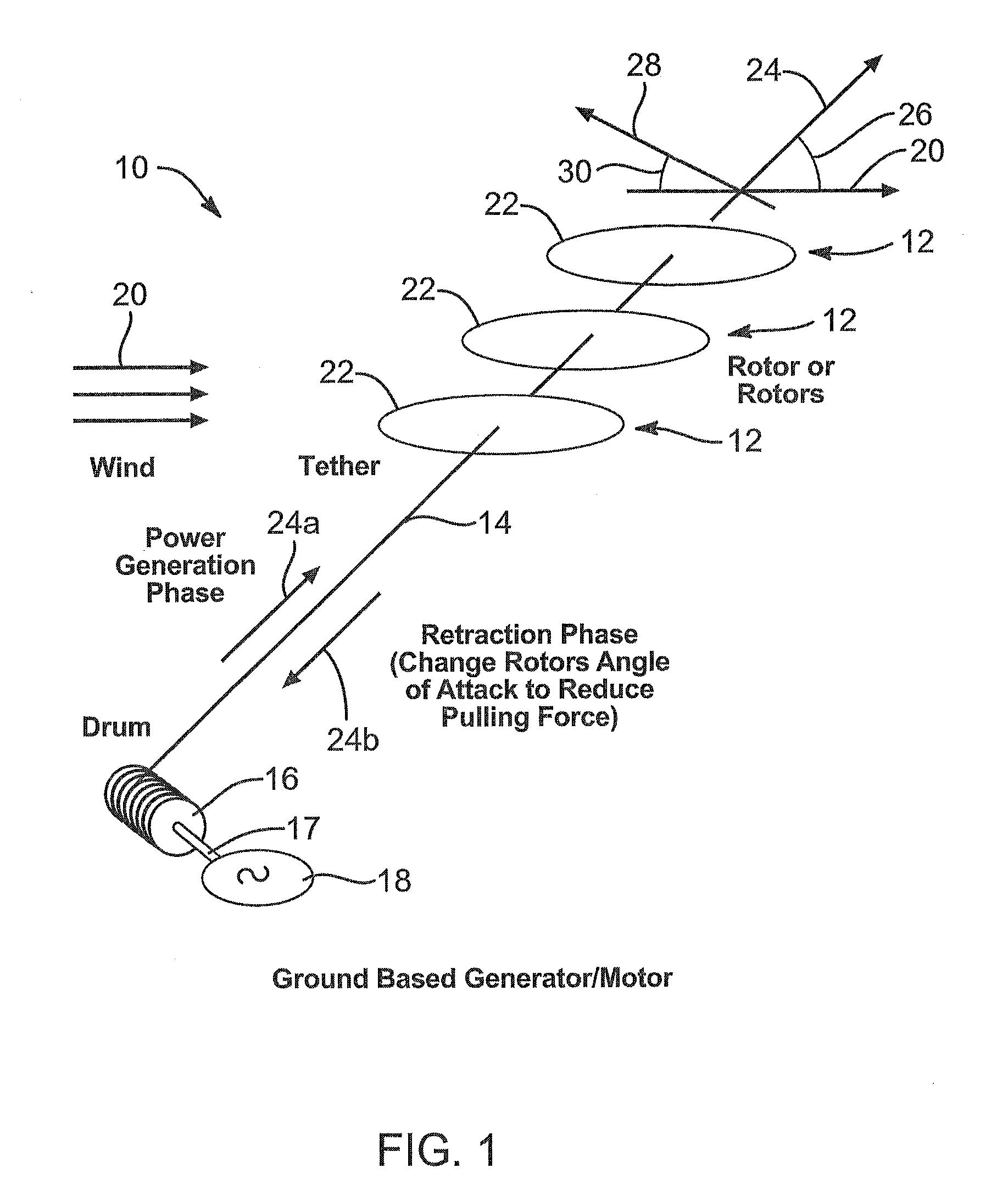
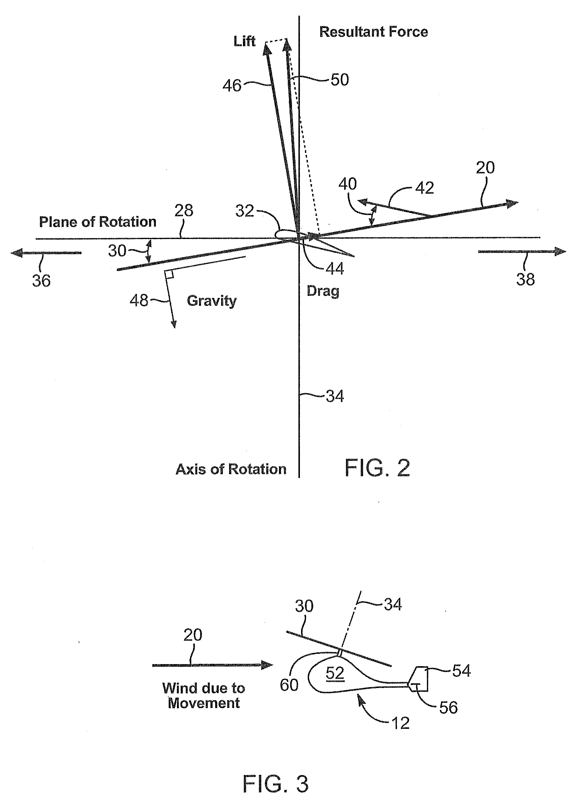
[0049]An autogyro typic...


PUM


Abstract

A control system for a power generation apparatus and method may fly a rotorcraft rotary wing at an altitude above the nap of the earth. A tether, suitably strong and flexible, connected to the rotorcraft framing is pulled with a force generated by the rotary wing. The force is transmitted to a ground station that converts the comparatively linear motion of the tether being pulled upward with a lifting force. The linear motion may be transferred to a rotary motion in the ground station to rotate and electrical generator. The tether may be retrieved and re-coiled by controlling the rotorcraft aircraft to basically fly down at a speed and lift force to support recovery of the rotorcraft at a substantially reduced force compared to the larger lifting force in effect during the power-developing payout of the tether. Moreover, the duty cycle of such a system is substantially increased over any terrestrially based or tower-mounted wind turbine mechanisms.

Description

RELATED APPLICATIONS[0001]This application claims the benefit of co-pending U.S. Provisional Patent Application Ser. No. 61 / 183,901, filed on Jun. 3, 2009 for a TETHERED ROTARY FOIL POWER GENERATION, and co-pending U.S. Provisional Patent Application Ser. No. 61 / 253,925 filed on Oct. 22, 2009 for AUTOGYRO POWER GENERATION APPARATUS AND METHOD, both of which provisional patent applications are hereby incorporated by reference in their entiretiesBACKGROUND[0002]1. The Field of the Invention[0003]This invention relates to control of aircraft, and, more particularly to control of tethered rotorcraft as a mechanism to generate power.[0004]2. The Background Art[0005]Autogyro aircraft are a form of powered or unpowered rotorcraft, typically having one or more auto-rotating airfoils or blades. Helicopters have one or more powered, rotating airfoils or blades. Gyrodynes power the rotor in preparation for takeoff, then fly with a freewheeling rotor (rotary wing) in flight pushed by a pusher p...

Claims


Application Information

Patent Timeline
Patent Type & Authority Applications(United States)
IPC IPC(8): B64C31/06
CPCB64C27/02B64C39/022Y02E10/728F05B2240/921F03D11/04F03D13/20Y02E10/72B64U10/60F03D9/25F03D1/025
Inventor CALVERLEY, GRANT
Owner CALVERLEY GRANT
Why Eureka
Try Eureka