Optical fiber for single-mode operation

a single-mode operation, optical fiber technology, applied in the field of optical fiber communications, can solve the problems of increasing the cost of splicing, and difficulty in splicing, so as to facilitate mode coupling, enhance the inherent selectivity, and reduce the incidence

Inactive Publication Date: 2005-01-04
FURAKAWA ELECTRIC NORTH AMERICA INC
View PDF5 Cites 20 Cited by
  • Summary
  • Abstract
  • Description
  • Claims
  • Application Information

AI Technical Summary

Benefits of technology

The invention takes advantage of the loss mechanism, which has plagued effort on perturbed multimode fiber, to assure single-mode behavior in a “few-mode” fiber core—in a core of sufficient size to support from one to three higher-order LP modes in addition to the fundamental mode. The “Enhanced Single-Mode Fiber” (“ESMF”) of the invention, like the perturbed multi-mode fiber of the prior art, depends on a series of perturbations to facilitate mode coupling, but spaces perturbations to deliberately couple the highest-order guided mode with an unguided or “cladding mode” and, so, to induce radiation of—i.e., to strip—that mode from the fiber.
It remains to restrict that induced selective loss to intended mode(s) to be stripped. Stepwise coupling with lower order modes is of lessening incidence with decreasing mode number, as dictated by the basic nature of the mode coupling phenomenon. The invention provides for enhancing that inherent selectivity by appropriate cross-sectional index profile design—importantly to discourage coupling with the fundamental mode. This is accomplished by taking advantage of the dependence of radial positioning of energy concentration on mode-order—by providing one or more profile “index features,” so positioned as to selectively change the effective index-of-refraction of a particular mode. Increasing index of the fundamental mode, relative to that of the second mode, lessens likelihood of coupling and reduces loss of the fundamental mode.
A variety of other profile features—dimensional or compositional—more abrupt, or otherwise departing from the primary profile design—may advance the fundamental objective, or serve additional purposes. Features may aid in assuring microbending and macrobending performance to meet specification requirements, e.g., performance equal to that required of traditional single-mode fiber.
ESMF—in its simplest form, of conventional step-index or continuously-profiled-index core—now of increased core size, and consequently of increased MFR, as compared with traditional single-mode fiber—exhibits operating advantages due to lessened impact of nonlinearities, such as 4-Wave Mixing and Stimulated Brillioun Scattering. Other advantages, also related to larger core size, include improved production yield and ease of installation. Illustratively, in terms of a common silica material / fiber design, core radius may be increased from a characteristic value of 4.5 microns (μm), for traditional single-mode fiber (TSMF), to 8.8 μm for a representative ESMF design—equivalently, MFR may be increased from 5.8 μm to 8.0 μm, both as measured at a wavelength of 1550 nanometers (nm)—without significantly impacting other fiber parameters. (The size relationship between MFR and core size is described, e.g., in “Optical Waveguide Theory”, A. W. Snyder and J. D. Love, chapter 15—Chapman Hall, 1983.)
The major thrust of the invention has been described—accommodation of a larger-than-conventional core in a single-mode fiber. Means for maintaining the various forms of loss, to enable the new fiber to meet specification requirements for conventional fiber, are provided for. Accordingly, the new fiber may be incorporated in state-of-the-art circuitry without further improvisation. ESMF, with its large core, has values of chromatic dispersion more nearly approaching bulk values—values sufficient to lessen limitations of 4 Photon Mixing. Provided with dispersion-compensating fiber, for controlling pulse-spreading, it readily meets circuit requirements.

Problems solved by technology

Needed small core size, and related small mode field size, however, complicate fabrication as well as installation and operation of commercial single-mode fiber.
In installation, small core size makes splicing more difficult.
In operation, resulting small mode field radius (MFR) and associated large signal density increases consequences of nonlinearities.
While broadly recognized, little progress has been made toward alleviating difficulties associated with small core size.
This results in both increased microbending loss and increased cabling loss.
The origin of the problem—conversion of laser-generated, single-mode light pulses into multimode pulses by fiber imperfections—has defied correction.
Unfortunately, this line of effort has, until now, led to significantly added fiber loss.
Wanted coupling of bound modes has been accompanied by direct or stepwise coupling to leaky (unguided) cladding modes, with consequent added loss sufficient to disqualify the approach.

Method used


Image

  • Optical fiber for single-mode operation
  • Optical fiber for single-mode operation
  • Optical fiber for single-mode operation

Examples


example 1

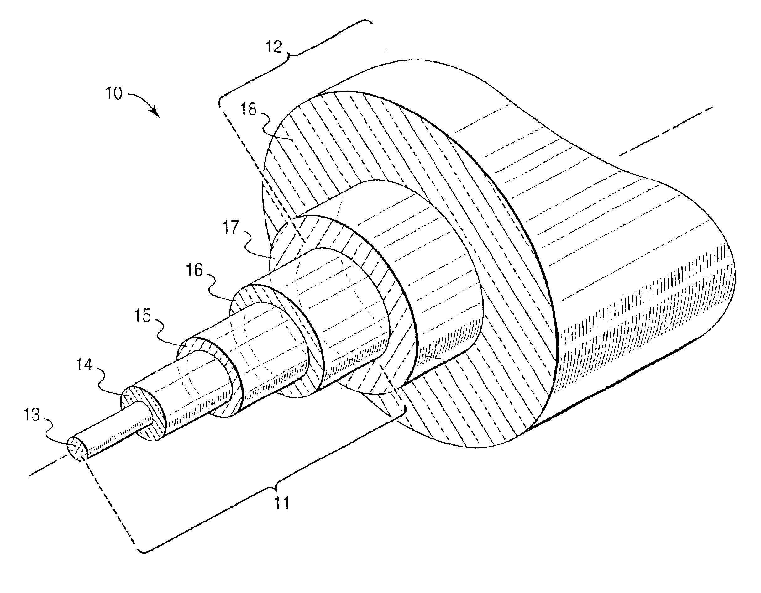
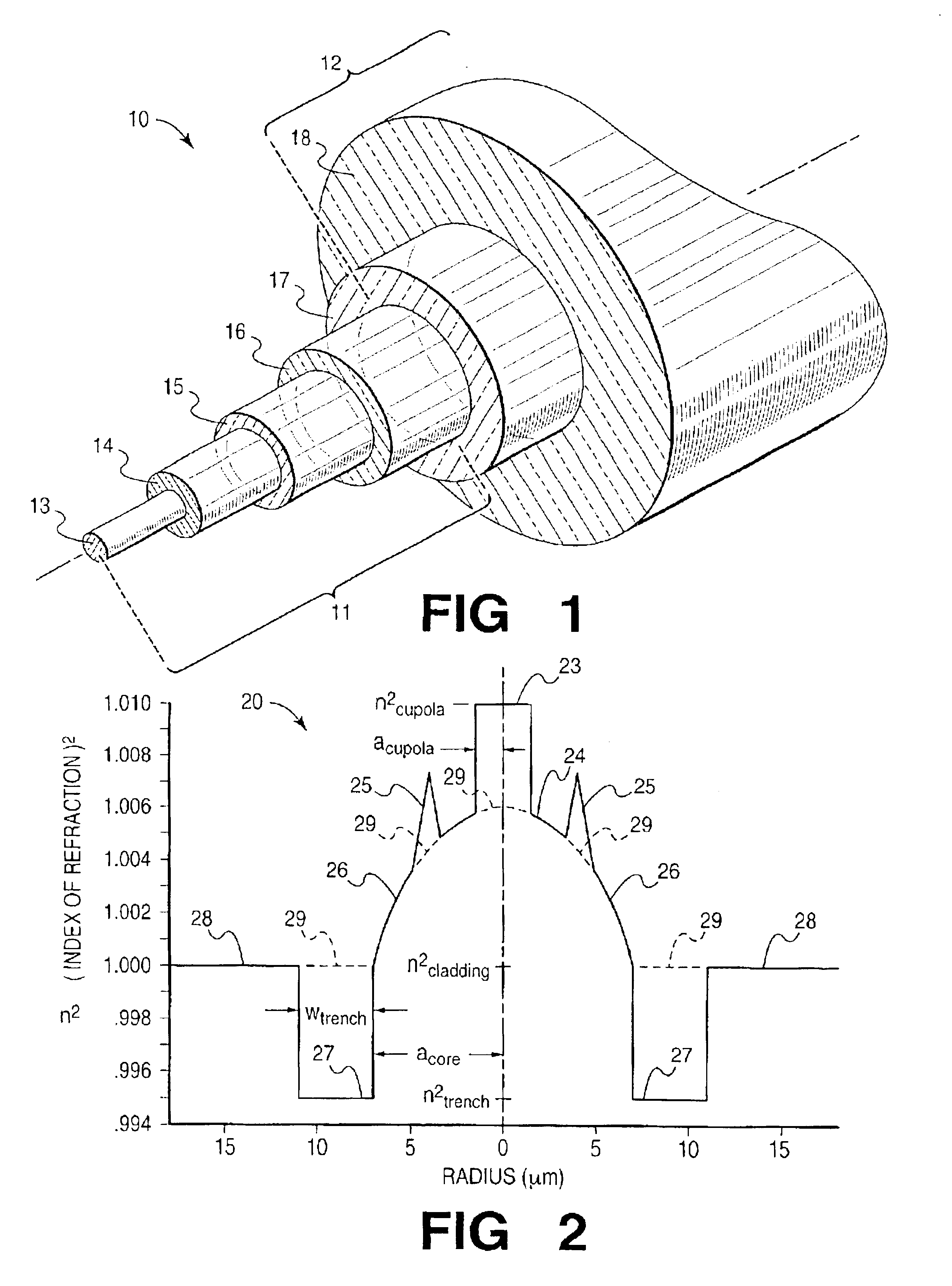
A fiber of the profile of FIG. 2, is viewed as derived from an unfeatured fiber of near-2 α profile with cladding of undoped silica—accordingly n2cladding=1. Parameter values, in the order listed in Table 1, are: acore=7 μm, n2cupola=1.01, acupola=1.5 μm, n2trench=0.995, wtrench=4 μm. Operating at carrier wavelength, λ0=1550 nm, MFR=6.5 μm with macrobend and microbend loss performance equal to or better than that of TSMF.

Metro ESMF Design

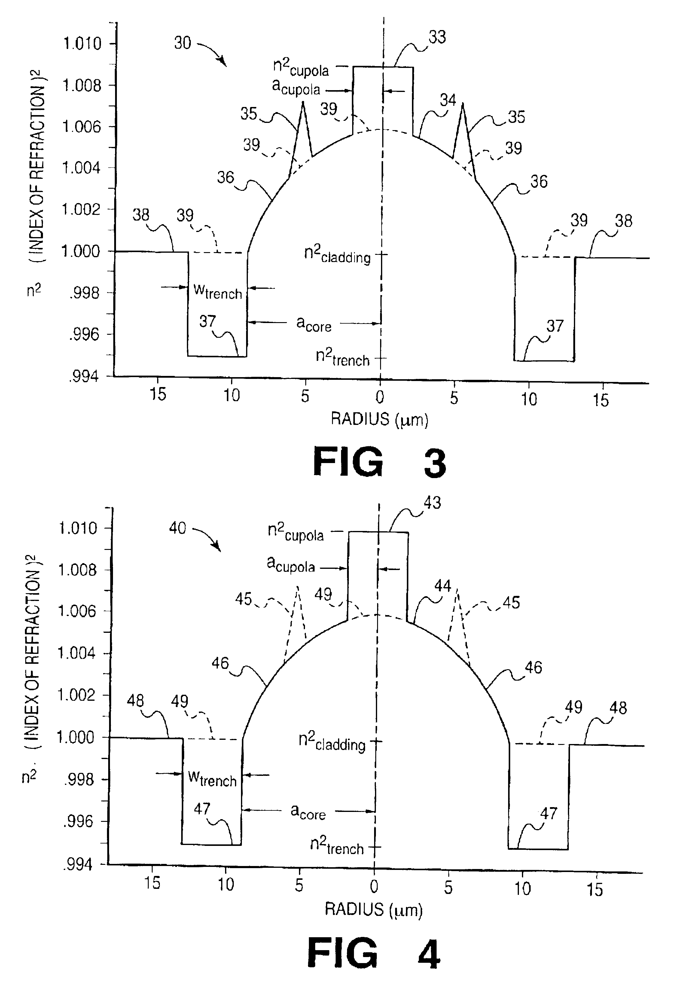
FIG. 3 is a cross-sectional, index-of-refraction, profile plot considered in discussion of ESMF for medium and short distance transmission. With span lengths no greater than 50 km, concern for fiber insertion loss is lessened, so that operation over a broadened wavelength range becomes viable. The operating range now includes that associated with the nominal carrier, λ0=1310 nm, so resulting in a total range of 1100-1700 nm (excepting a range centered at the 1385 nm water peak if not eliminated). Coordinates are those of FIG. 2—radial distance from ...

example 2

A fiber of the profile of FIG. 3, is viewed as derived from an unfeatured fiber of near-2 α profile with cladding of undoped silica—accordingly n2cladding=1. Parameter values, in the order listed in Table 2, are: acore=9 μm, n2cupola=1.009, acupola=2.0 μm, n2trench=0.995, wtrench=4 μm. Operating at carrier wavelength, λ0=1110 nm, MFR=7.5 μm: at λ00=1550 nm, MFR>8.2 μm.

Access and Enterprise ESMF Design (“Local Transmission”)

FIG. 4 is a cross-sectional, index-of-refraction, profile plot considered in discussion of ESMF for local transmission—e.g., for span length typically ≦10 km. Likely of lesser commercial significance than long haul or metro, local ESMF is included for the possibility that its very broad single-mode operating range may finally lead to replacement of multimode fiber now commonly used in systems designed for operation at λ0=850 nm. As in FIGS. 2-3, coordinates are: radial distance from the fiber axis in units of μm on the abscissa; and n2, the second power of the ind...

example 3

A fiber of the profile of FIG. 4, is viewed as derived from an unfeatured fiber of 2 α profile with cladding of undoped silica—accordingly n2cladding=1. Parameter values, in the order listed in Table 3, are: acore=9 μm, n2cupola=1.01, acupola=2 μm, n2trench=0.995, wtrench=4 μm. Operating at carrier wavelength, λ0=850 nm, MFR=7 μm at λ0=1550 nm, MFR>9 μm.

7. Dispersion Tailoring

Without specific design provision, ESMF, with its larger core, tends toward values of chromatic dispersion approaching bulk values. Provided with appropriate lengths of Dispersion Compensating Fiber, it meets circuit requirements. Initial commercial use may, accordingly, be in conjunction with DCF.

Design means are available for adjusting chromatic dispersion in ESMF to meet requirements of Non-Zero Dispersion Fiber (NZDF), e.g., TrueWave® fiber—e.g., for yielding dispersion within the now-specified range of 1.5-8 ps / nm-km as measured at 1550 nm. Dispersion management features, most effectively situated within t...


PUM

PropertyMeasurementUnit
radial distanceaaaaaaaaaa
core radiusaaaaaaaaaa
radial distanceaaaaaaaaaa

Abstract

A single-mode fiber of increased core size consists of a “few-mode” fiber, of core size sufficient for guiding up to three high-order modes in addition to the fundamental mode, by interposing perturbations of such spacing along the fiber, as to selectively couple any such high-order modes to (unguided) cladding modes, thereby rejecting all but the fundamental mode. Unwanted coupling of the fundamental mode, leading to added fiber loss, is minimized by appropriate refractive index profile design.

Description

FIELD OF THE INVENTIONOptical fiber communications.BACKGROUND OF THE INVENTIONIn a period of three decades, optical fiber has displaced copper wire as the transmission medium of choice for long distance communications. Production, now multi-national, is at a rate of millions of kilometers per year. Indications are that use will continue to expand, beyond terrestrial and underwater long distance, to medium distance and to local usage including “fiber to the home”. General acceptance of digital communications has furthered use of fiber for transmission of picture and data as well as for voice.For many purposes, the initially introduced multimode fiber has been supplanted by single-mode fiber with substantial improvement in bandwidth. Recent advances in fiber design have, for the most part, been directed to single-mode operation. Needed small core size, and related small mode field size, however, complicate fabrication as well as installation and operation of commercial single-mode fib...

Claims


Application Information

Patent Timeline
Patent Type & Authority Patents(United States)
IPC IPC(8): G02B6/036G02B6/02
CPCG02B6/03666
Inventor WHITE, IAN A.
Owner FURAKAWA ELECTRIC NORTH AMERICA INC
Why Eureka
Try Eureka