[0025] The forgoing objects are met in a
new device and method for the treatment of
morbid obesity. This
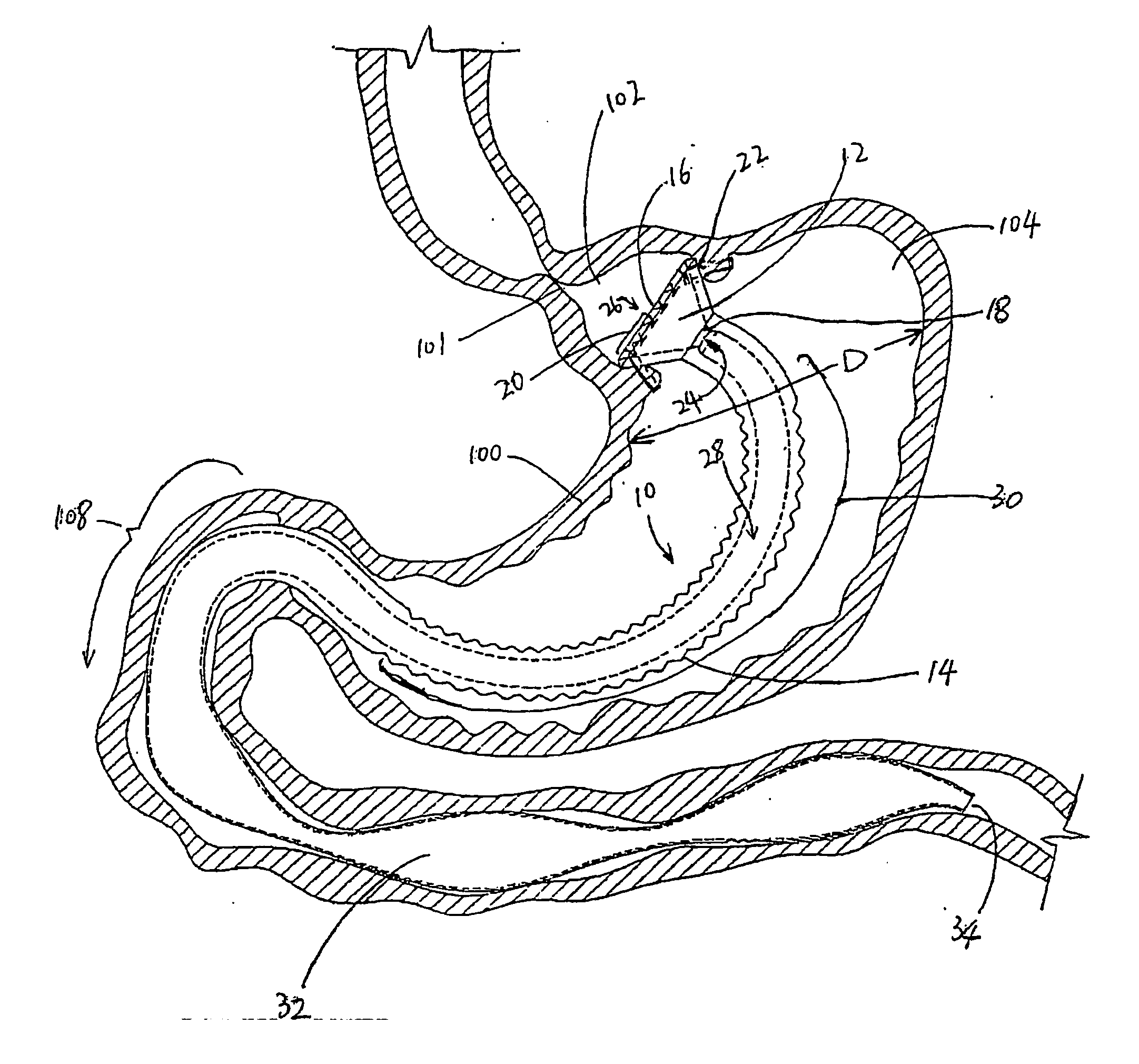
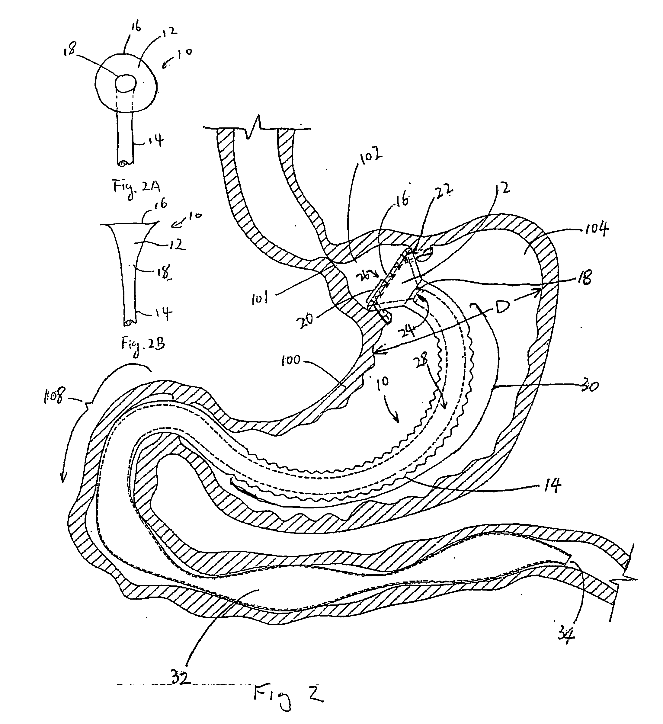
new device and method achieve the restrictive aspect of vertical banded gastroplasty and roux-en-y gastric bypass through formation of a stomach pouch substantially smaller than the natural stomach. This is achieved through installation of an annular element, preferably a funnel-like shaped or conical-shaped element, which is circumferentially attached to the stomach wall dividing the stomach into two regions: the
esophagus-end chamber and the
pylorus-end chamber. In a preferred embodiment, the conical-shaped element is equipped with a reinforced
flange extending from a proximal end of the conical-shaped element. The
flange is capable of accepting sutures or staples. In one preferred embodiment, the
flange is turned inward to accept the anvil element of a circular anastomotic stapler. In a preferred embodiment, the volume of the esophagus-end chamber (pouch) between the lower
esophageal sphincter and the conical element is equivalent to the pouch formed in standard surgical practice for roux-en-y gastric bypass: about 30 ml to 70 ml, thus limiting the amount of
food intake of a patient.
[0026] The conical-shaped element includes an interior hollow region having an opening at its distal end for passage of swallowed food into the remainder of the
gastrointestinal tract (GI tract). In one embodiment, this opening is a substantially circular orifice with a
diameter equivalent to the target
diameter of the anastomotic
stoma formed surgically in gastric
bypass surgery, approximately 8 to 12 mm. In a preferred embodiment, this opening includes a valve
assembly for closing the opening to prevent spontaneous passage of swallowed food or liquid until the natural digestive regulation and coordination processes trigger movement and contraction of the stomach wall in the esophagus-end chamber. The controlling of the opening is preferably accomplished by the presence of a valve that requires
positive pressure differential between the proximal side of the valve and the distal side of the valve to open (for the purpose of this description, proximal shall mean closer to the mouth end of the
digestive tract and distal shall mean closer to the colon end when the device is in use). Opening pressure for this
stoma valve should be greater than the pressure caused by gravity on a standing column of food within the pouch (1 to 5 mmHg) and less than the continent manometric pressure of-the lower
esophageal sphincter (about 15 to 30 mmHg in healthy humans.) In one preferred embodiment, this valve has a higher opening pressure in the retrograde direction than in the forward direction to reduce the incidence of
reflux into the esophagus. In another preferred embodiment, the stoma valve employs a valve with
hysteresis such that the valve opens fully at an initial
cracking pressure and closes fully at a closing pressure lower than the
cracking pressure, thereby offering more complete emptying of the pouch with smaller stomach wall contraction pressures. In another preferred embodiment, the pouch stoma valve communicates with the
pyloric sphincter such that the stoma valve opens upon relaxation of the
pyloric sphincter muscle and closes in
sync with
pyloric sphincter muscle pressure.
[0027] In another preferred embodiment, further elements are added to provide a malabsorptive aspect to the device. In one embodiment, the malabsorptive aspect is achieved by providing an elongated flexible tube extending from the distal end of the conical-shaped element to a distal end. The elongated flexible tube has a length so that the tube passes the pylorus of the patient and the distal end is positioned in the intestine when the device is in use. The elongated flexible tube defines an inner central lumen which establishes communication between the distal stoma orifice or the valve of the conical-shaped element and the intestines distal to the pylorus, but not in communication with the pylorus-end chamber between the distal side of the conical-shaped element and the pyloric
sphincter, thereby isolating this otherwise absorptive stomach region from contact with food. In one preferred embodiment, the tube is made of a flexible material such that the natural muscular movement of the stomach creates a pumping action to the tube to assist in transporting food through the lumen. In one preferred embodiment, the portion of the lumen transiting the pyloric
sphincter has sufficient diametric rigidity to
resist collapse from pyloric
sphincter pressure. In other embodiments, particularly the embodiment without a stoma valve at the distal end of the conical-shaped element, the region transiting the pyloric sphincter is sufficiently pliable to allow the tube to collapse and the lumen to be closed under pyloric sphincter pressure.
[0028] In one embodiment, the
diameter of the flexible tube is sized to provide a space between the outer surface of the tube and the circumference of the pylorus when the sphincter is in a relaxed state, to allow passage of any excess stomach acid that may have accumulated in the pylorus-end chamber. In other embodiments, passageways are provided on the outer surface of the flexible tube, for example, grooves defined on the outer surface of the tube, to allow passage of the stomach acid when the pyloric sphincter is in the
closed state. In another preferred embodiment, passageways are provided to allow stomach acid to pass one-way from the pylorus-end chamber into the inside of the lumen to assist in breakdown of food within the lumen.
[0029] In one preferred embodiment, the elongated flexible tube extends beyond the pylorus and ends in the upper
duodenum. In another preferred embodiment, the elongated flexible tube transits a portion of the
duodenum, which portion has a length equivalent to the length of the portion of the
duodenum bypassed in standard practice of a roux-en-y gastric
bypass surgery (approximately 50 to 200 cm), thereby rendering this portion of the intestine malabsorptive. In a further preferred embodiment, the elongated flexible tube includes at least a portion that is collapsible under peristaltic pressure from the stomach or the intestinal wall, thereby allowing food to be transported through the lumen by means of stomach or
intestinal peristalsis. In another preferred embodiment, the collapsible portion starts from the proximal end of the duodenum to the distal end of the tube. In one preferred embodiment, the portion of the tube in the duodenum region is constructed such that it is in a naturally collapsed state, such as a flattened tube, with no
external pressure required to compress the tube closed. In another preferred embodiment, the tube is constructed such that the inner central lumen is in a naturally open state, such as a round tube, such that
external pressure is required to pinch the lumen closed and the lumen returns to the open state when
external pressure is removed. In another preferred embodiment, a portion of the tube which is disposed in the peristaltic portion of the duodenum when the device is in use is made of an elastic material. The portion of the tube may be compressed by the
peristalsis of the duodenum and the elastic wall of the tube forces tube to return to its naturally open state when the pressure from the duodenum
peristalsis is removed, thereby creating a negative pressure within the lumen to assist in propulsion of food in the distal direction and to assist in sucking stomach acid into the inside of the lumen through the one-way acid valve, if provided.
[0031] Preparation: An endoscopic suturing device such as the C. R. BARD ENDOCINCH™, or other endoscopic suturing device known to the art, will be used to place a plurality of sutures (10 to 12 sutures in a preferred embodiment) in the gastric cardiac region in a ring approximately 3 cm distal to the
gastroesophageal junction. The sutures will be 2 m long
polypropylene monofilament placed in a mattress configuration with a felt pledget. The suture tails, in pairs, will be passed through the circumference of the gastric bypass
prosthesis (GBP) attachment ring flange using a free needle. A
system of
cut-away tubes (i.e. drinking straws) may be used to organize the strands and prevent suture pair entanglement.

