Patient intreface assembly supported under the mandible

Active Publication Date: 2005-09-22
PHILIPS RS NORTH AMERICA LLC
View PDF29 Cites 263 Cited by
  • Summary
  • Abstract
  • Description
  • Claims
  • Application Information

AI Technical Summary

Benefits of technology

[0012] The hollow construction of the chin support enables the mask assembly to be inflated using pressure from the pressure generating device. The circular construction enables the patient to occlude one side of the chin support and still receive therapy from the opposite unoccluded side of the chin support. The flexible soft construction of the chin support does not cause substantial discomfort when the patient rolls onto the mask assembly during sleep. The mask assembly also eliminates visual obstructions and allows the use of eyeglasses.
[0013] The modular design of the mask assembly allows a variety of different patient interfaces to be used, such as nares elements, nasal masks, oral masks, and nasal/oral masks. The circular design of the chin mask such as it contacts and supports the patient's chin beneath or behind the mental protuberance provides increased support and stability without the use of an additional forehead support. The rotatable coupling between the chin mask and the patient interface allows the patient to position the patient interface in the most comfortable and effective position for the patient and helps prevent leaks. The chin support

Problems solved by technology

If these concerns are not addressed, the patient may avoid wearing the interface device, defeating the purpose of the prescribed pressure support therapy.
While the mask assembly shown in the '535

Method used


Image

  • Patient intreface assembly supported under the mandible
  • Patient intreface assembly supported under the mandible
  • Patient intreface assembly supported under the mandible

Examples


first embodiment

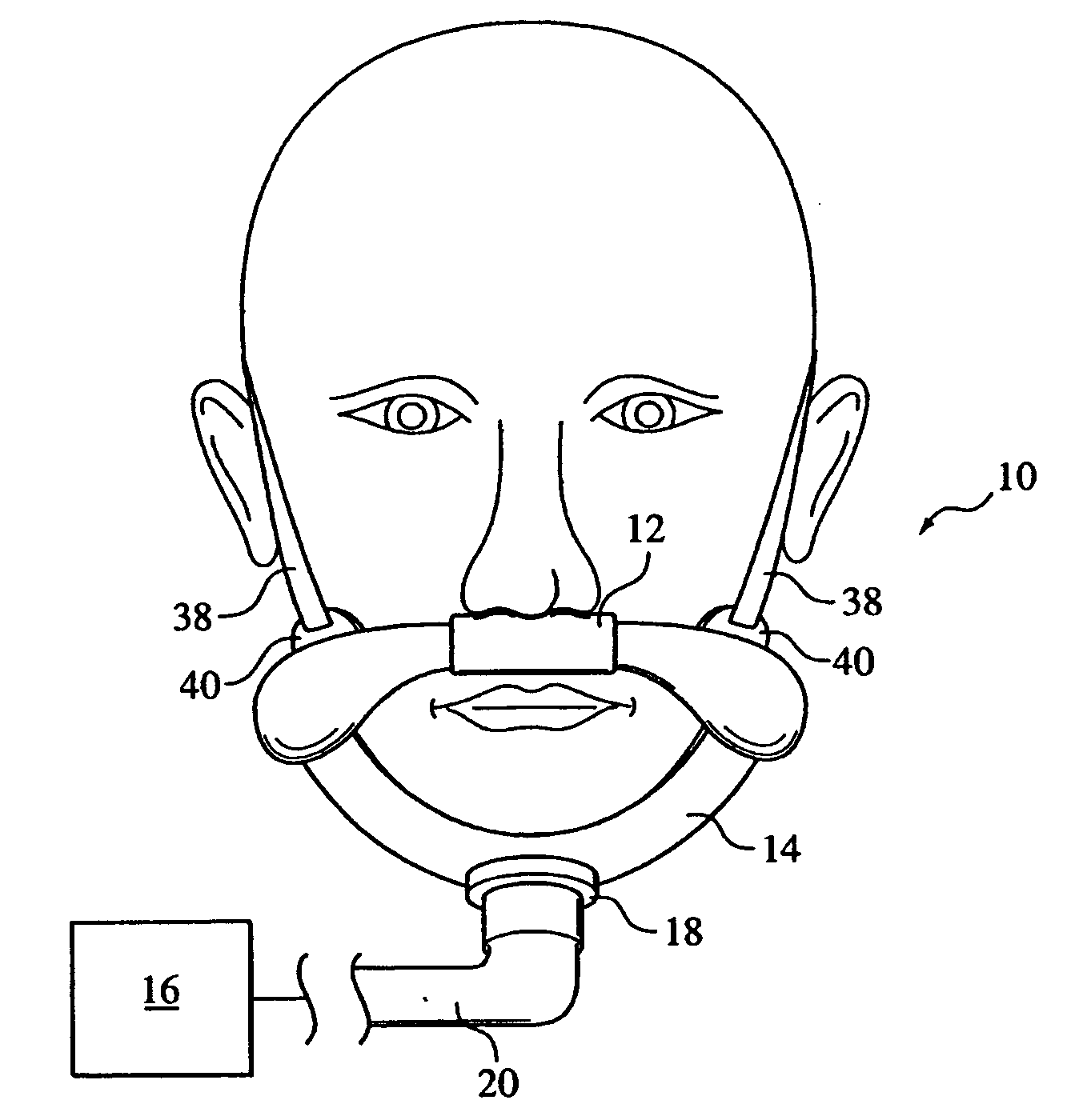
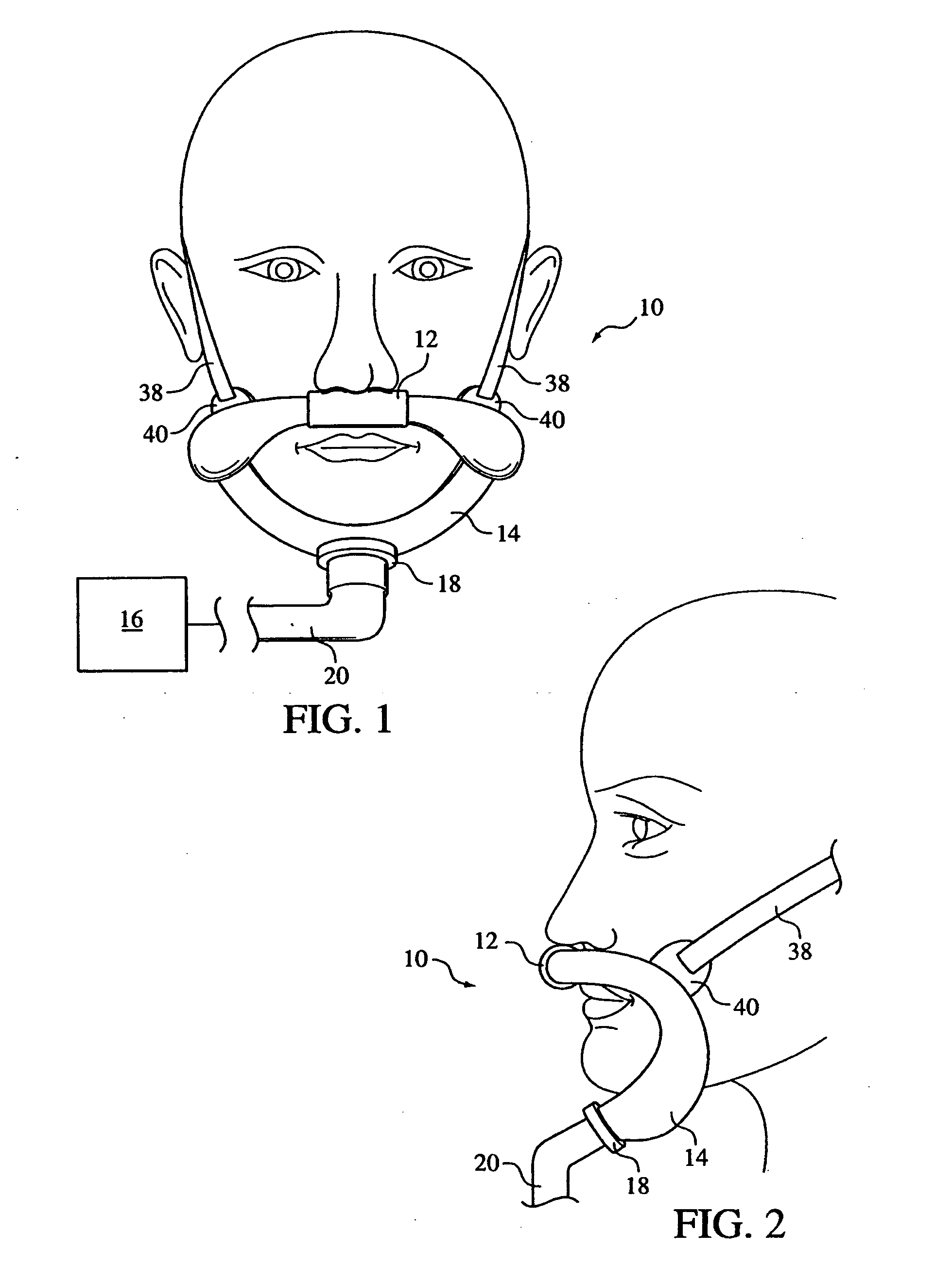
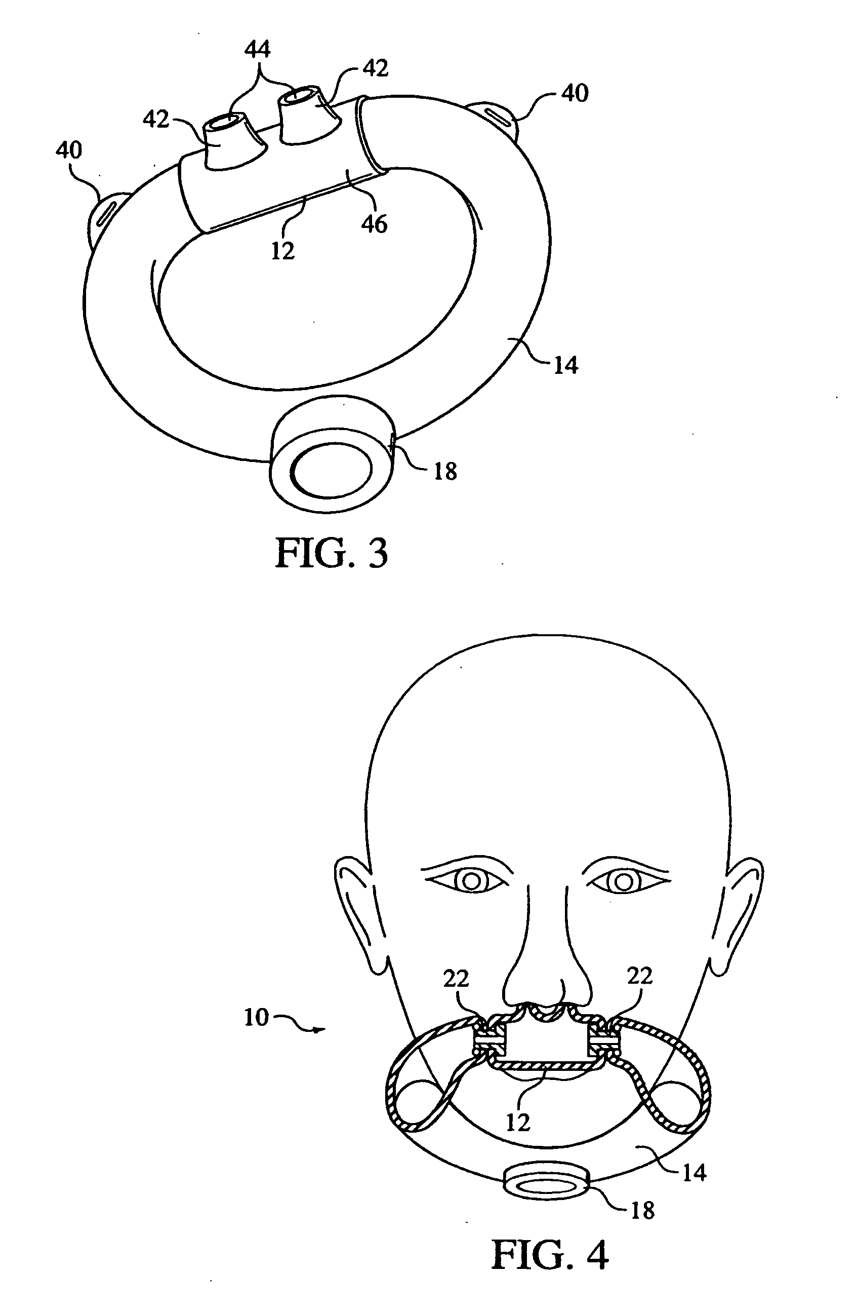
[0070] A patient interface assembly 10 according to the present invention is shown in FIGS. 1-6 and includes a patient interface 12 fluidly and rotatably coupled to a chin support 14. Patient interface assembly 10 communicates a flow of breathing gas between a patient's airway and a pressure generating system 16, such as a ventilator, CPAP device, or variable pressure device, e.g. an auto-titrating device, proportional assist ventilation (PAV) device, proportional positive airway pressure (PPAP) device, C-Flex device, Bi-Flex device, or a BiPAP® device manufactured and distributed by Respironics, Inc. of Murrysville, Pa., in which the pressure provided to the patient varies with the patient's respiratory cycle so that a higher pressure is delivered during inspiration than during expiration, or other pressure support device.

[0071] Chin support 14 is preferably formed from a hollow chambered support made from a flexible plastic compound and extends from either side of patient interfac...

third embodiment

[0094]FIGS. 19-26 illustrate a patient interface assembly 160 according to the principles of the present invention. Patient interface 160 includes a patient interface 162 fluidly and rotatably coupled to a chin support 164, which is similar to chin support 14 discussed above with respect to FIGS. 1-5. Chin support 164 includes a patient contacting portion 166 and an exterior portion 168 that define a hollow tube suitable for communicating a flow of gas from a patient circuit coupling port 170 to patient interface 162. Patient contacting portion 166 is preferably formed from a soft substance, such as silicon, and / or includes a soft, patient contacting substance disposed thereon to maximize the comfort of the contact between the patient and the patient interface assembly.

[0095] For example, the present invention contemplates providing a removeable foam or fabric slip-on cover (not shown) that is provided over patient contacting portion 166. Such a slip-cover would provide benefits suc...

fourth embodiment

[0113]FIGS. 30-31 illustrate a patient interface assembly 250 according to the principles of the present invention. Patient interface assembly 250 includes a patient interface 252 coupled to a chin support 254. Patient interface 252 corresponds to any of the patient interfaces discussed herein and is preferably rotatably coupled to chin support 254 at exhaust port pieces 256 that include a plurality of openings that allow a flow of gas to be exhausted from the patient interface assembly.

[0114] Chin support 254 includes a support member 258 to which the other elements of the chin support, such as the exhaust port pieces, are mounted. Support member 258 is preferably rigid or semi-rigid so that it can support the components of the patient interface assembly. The patient contacting side of support member 258 is preferably formed from a soft substance, such as silicon, or includes a soft, patient contacting substance disposed thereon to maximize the comfort of the contact between the pa...


PUM


Abstract

A patient interface system having a patient interface and chin support system for supporting the patient interface on the patient and for supplying a flow of gas from a patient circuit to the patient interface. In one embodiment, the chin support is formed from flexible hollow chambered support and extends from either side of the patient interface curving downwardly in front of the patient's cheeks, around the outside of the patient's mouth, to a position beneath the patient's mandible. In another embodiment, the chin support is coupled to a conduit that is coupled to the patient interface. The chin support includes at least a portion that is disposed under the patient's mandible.

Description

CROSS-REFERENCE TO RELATED APPLICATIONS [0001] This application claims priority under 35 U.S.C. § 119(e) from provisional U.S. patent application No. 60 / 542,750 filed Feb. 6, 2004, the contents of which are incorporated herein by reference.BACKGROUND OF THE INVENTION [0002] 1. Field of the Invention [0003] The present invention generally relates to a patient interface assembly for use in a pressure support system, and, in particular, to a patient interface assembly that is supported under at least a portion of the patient's mandible, and to a gas delivery system that incorporates such a patient interface assembly. [0004] 2. Description of the Related Art [0005] There are numerous situations where it is necessary or desirable to deliver a flow of breathing gas non-invasively to the airway of a patient, i.e., without intubating the patient or surgically inserting a tracheal tube in their esophagus. For example, it is known to ventilate a patient using a technique known as non-invasive...

Claims


Application Information

Patent Timeline
IPC IPC(8): A61M16/06A61M16/08A62B7/00A62B18/08
CPCA61M16/0666A61M16/0683A61M16/0694A61M2210/0618A62B18/084A61M16/0816A61M16/0616A61M16/065A61M16/0655A61M16/0875A61M2016/0027A61M16/0003A61M16/0622A61M16/0883
Inventor MATULA, JEROME JR.HO, PETER CHI FAIEATON, JASON P.DIACOPOULOS, ELIAS G.RADNEY, STEVEN B.
Owner PHILIPS RS NORTH AMERICA LLC
Why Eureka
Try Eureka