Iron With A Fill Opening Fitted With A Seal

a technology of iron and fill opening, applied in the field of irons, can solve the problems of dirt and discomfort for users, spraying water, and accumulation of water on the internal surface,

Active Publication Date: 2020-09-10
SEB SA
View PDF0 Cites 0 Cited by
  • Summary
  • Abstract
  • Description
  • Claims
  • Application Information

AI Technical Summary

Benefits of technology

[0007]To this end, the present invention relates to an iron comprising a case fitted with a heel located in a rear part of the case, on which the iron can rest during the inactive ironing phases, an internal reservoir, an fill opening fluidly connected to the internal reservoir and opening into a front surface of the iron case, a movable fill opening between a closed position in which the fill opening covers the fill opening and prevents filling the internal reservoir, and an open position in which the fill opening at least partially releases the fill opening and allows the filling of the internal reservoir, a seal comprising a mounting part fixed to the fill opening and a sealing part which is configured to seal the fill opening when the fill opening is in the closed position, and a vent provided on the fill opening, the vent opening to the outside of the iron and being fluidly connected to the internal reservoir when the fill opening is in the closed position, characterized in that the seal includes a barrier, part which extends into the internal reservoir when the fill opening is in the closed position, and a ventilation orifice, which is fluidly connected to the vent and which opens into the internal reservoir when the fill opening is in the closed position, the barrier part and the ventilation orifice being configured so as to prevent liquid from flowing from the internal reservoir and through the vent when the fill opening is in the closed position and the iron rests on the heel.
[0008]Such a configuration of the iron, and in particular of the barrier part and the ventilation orifice, avoids an accumulation of water droplets near the fill opening and considerably reduces, and even eliminates, the risk of water flowing through the ventilation orifice when the iron is moved from a position of use to a position in which the latter rests on its heel. Consequently, the seal, according to this invention, prevents the flow of water droplets through the vent and along the exterior surface of the fill opening and the exterior surface of the case.
[0010]According to one embodiment of the invention, the barrier part and the ventilation orifice are configured so as to prevent liquid from flowing from the internal reservoir and through the ventilation orifice when the fill opening is in the closed position and the iron rests on the heel.
[0011]According to one embodiment of the invention, when the fill opening is in the closed position, the ventilation orifice is oriented substantially opposite the heel of the iron. Such a position of the ventilation orifice further limits the risks of liquid flowing through the vent.
[0013]According to one embodiment of the invention, when the fill opening is in the closed position and the iron rests on the heel, the outlet of the ventilation orifice which opens into the internal reservoir is located at a height higher than that of the vent. Such a configuration of the ventilation orifice further limits the risks of liquid flowing through the vent.
[0020]According to one embodiment of the invention, the barrier part comprises a side wall, extending from the sealing part and in the direction of the internal reservoir when the fill opening is in the closed position, and a barrier wall which extends from the side wall and transversely to the side wall. Such an arrangement of the barrier part considerably reduces the risks of liquid flowing through the ventilation orifice.

Problems solved by technology

However, this configuration of the seal induces a spray of water and an accumulation of water on the internal surface of the internal cavity when the iron is moved from a position of use in which the iron is substantially horizontal to a rest position in which the iron rests on its heel, due to the movement of liquid generated in the internal reservoir by the movement of the iron.
However, such an accumulation of water in the internal cavity of the seal causes liquid to flow through the vent and along the external surfaces of the fill opening and of the case, which are sources of dirt and discomfort for the user.

Method used


Image

  • Iron With A Fill Opening Fitted With A Seal
  • Iron With A Fill Opening Fitted With A Seal
  • Iron With A Fill Opening Fitted With A Seal

Examples


Embodiment Construction

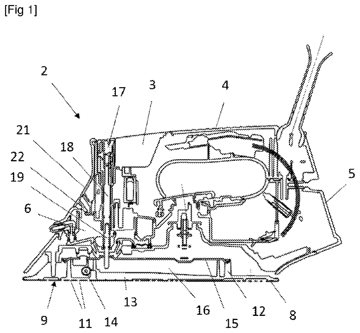
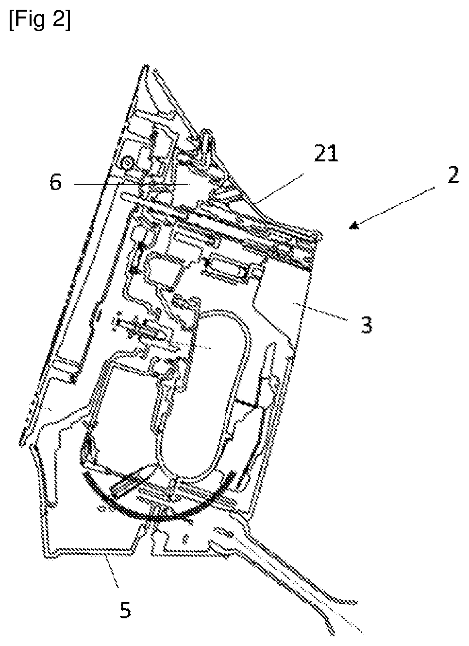
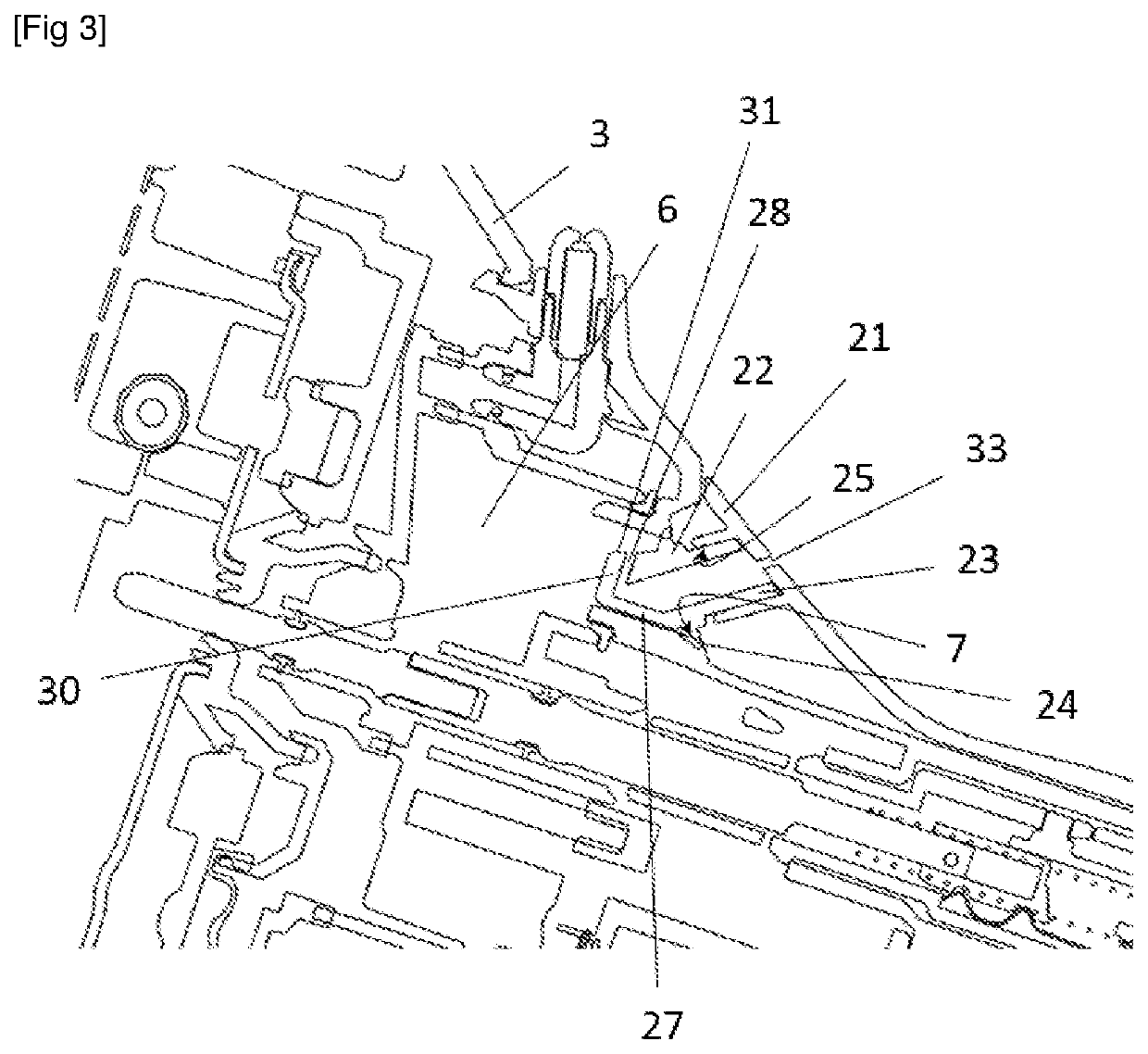
[0042]FIGS. 1 to 5 show an iron 2 comprising a case 3 comprising in particular a gripping part 4 and a heel 5 which is located in a rear part of the case 3 and on which the iron 2 can rest during the inactive ironing phases.

[0043]The iron 2 further comprises an internal reservoir 6 integrated in the case 3, and a fill opening 7 fluidly connected to the internal reservoir 6 and opening into a front surface of the case 3. The fill opening 7 is more particularly configured to allow at least the partial filling of the internal reservoir 6 with a liquid, such as water.

[0044]The iron 2 further comprises an ironing soleplate 8 provided with an ironing surface 9 which is substantially flat and with several steam outlet orifices 11 opening into the ironing surface 9.

[0045]The iron 2 also includes a heating body 12 integrated into a lower part of the case 3, and thermally and mechanically linked to the ironing soleplate 8. The heating body 12 may, for example, include a foundry 13, for exampl...


PUM


Abstract

An iron has a heel on which the iron can rest during inactive ironing phases, an internal reservoir, a fill opening fluidly connected to the internal reservoir, a fill opening cover movable between a closed position and an open position, a seal configured to seal the fill opening when the fill opening cover is in the closed position, and a vent which is fluidly connected to the internal reservoir when the fill opening cover is in the closed position. The seal includes a barrier part extending into the internal reservoir, and a ventilation orifice which is fluidly connected to the vent, and which opens into the internal reservoir, the barrier part and the ventilation orifice being configured so as to prevent liquid from flowing from the internal reservoir and through the vent when the fill opening cover is in the closed position and the iron rests on the heel.

Description

FIELD OF THE INVENTION[0001]The present invention relates to the field of irons.BACKGROUND OF THE INVENTION[0002]An iron has, in a known manner, a case equipped with a heel located in a rear part of the case and on which the iron can rest during the inactive ironing phases, an internal reservoir, a fill opening fluidly connected to the internal reservoir and opening into a front surface of the iron case, a movable fill opening between a closed position in which the fill opening covers the fill opening and prevents filling of the internal reservoir, and an open position in which the fill opening at least partially opens the fill opening and allows filling the internal reservoir, a seal comprising a mounting part fixed to the fill opening and a sealing part, which is configured to seal the fill opening when the fill opening is in the closed position, and a vent that is provided on the fill opening, the vent opening to the outside of the iron and being configured to be fluidly connecte...

Claims


Application Information

Patent Timeline
Patent Type & Authority Applications(United States)
IPC IPC(8): D06F75/14D06F75/36D06F75/38
CPCD06F75/14D06F75/38D06F75/36D06F79/00
Inventor COUET, BERTRANDDIAS, LAURENT D'OLIVIERA
Owner SEB SA
Why Eureka
Try Eureka