
Apparatus and method for measurement of hardenable material characteristics

Inactive Publication Date: 2007-09-13
HYDRONIX
View PDF11 Cites 11 Cited by
  • Summary
  • Abstract
  • Description
  • Claims
  • Application Information

AI Technical Summary

Benefits of technology

[0013]Preferably, the tightening member is a cylindrical sleeve threadably mounted on the main body of the retainer. Preferably, interengaging threads on the probe body and the retainer are threaded in the opposite sense to the threads between the tightening member and the main body of the retainer, so that tightening of the tightening member does not transmit, via the resilient member, a force tending to unfasten the probe. Preferably the resilient member is engaged under a lip of the body of the probe, so as to prevent the retaining member from being displaced outwardly, over the end of the probe body. A measuring instrument is preferably also provided, the instrument having terminals for connecting to the terminals of the sensor circuit carried by the measuring probe. Preferably, the probe and instrument have interengageable formations to ensure that the instrument and probe are in a predetermined relative orientation to facilitate interconnection of the terminals.
[0025]In a technique according to a preferred embodiment of the invention, measurements are taken at multiple different predetermined frequencies, rather than a single frequency. All the frequencies are selected to lie on one side (i.e. above or below) of the resonant frequency, and the measurements are then combined (e.g. by summing or averaging). By spreading the measurements over a band of frequencies it is possible to mitigate the effect of erroneous measurements due to interference at a particular frequency, and it becomes easier to meet regulatory requirements regarding emission characteristics.

Problems solved by technology

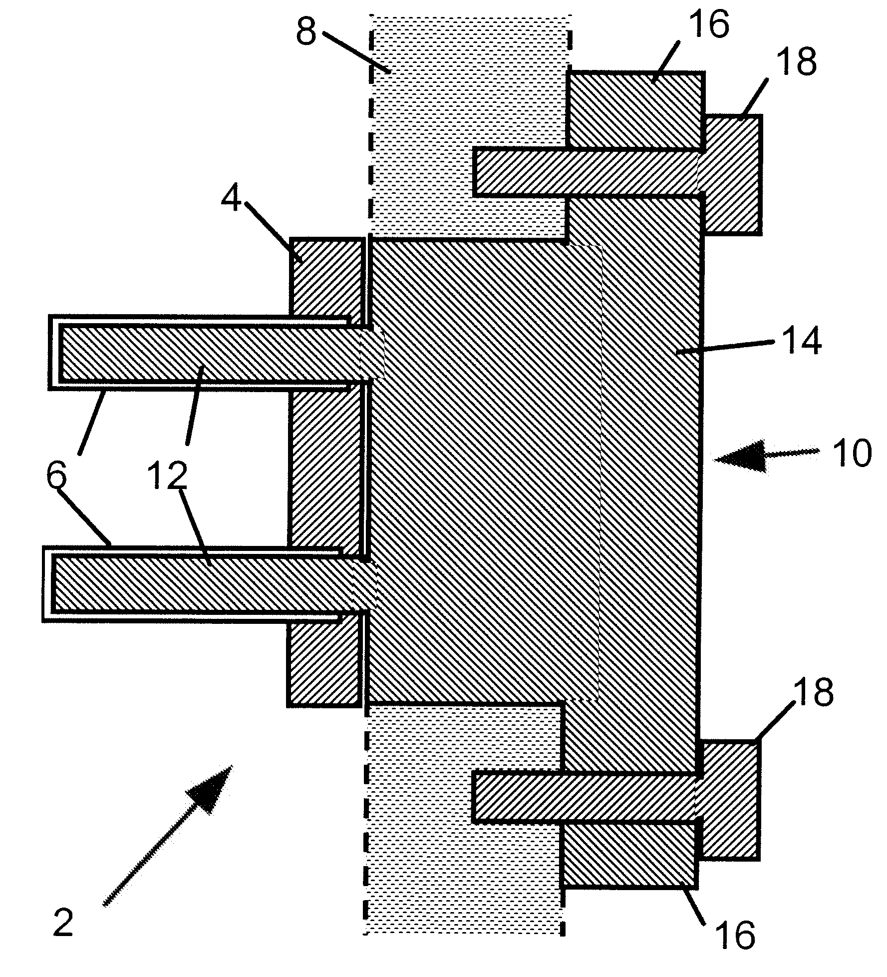
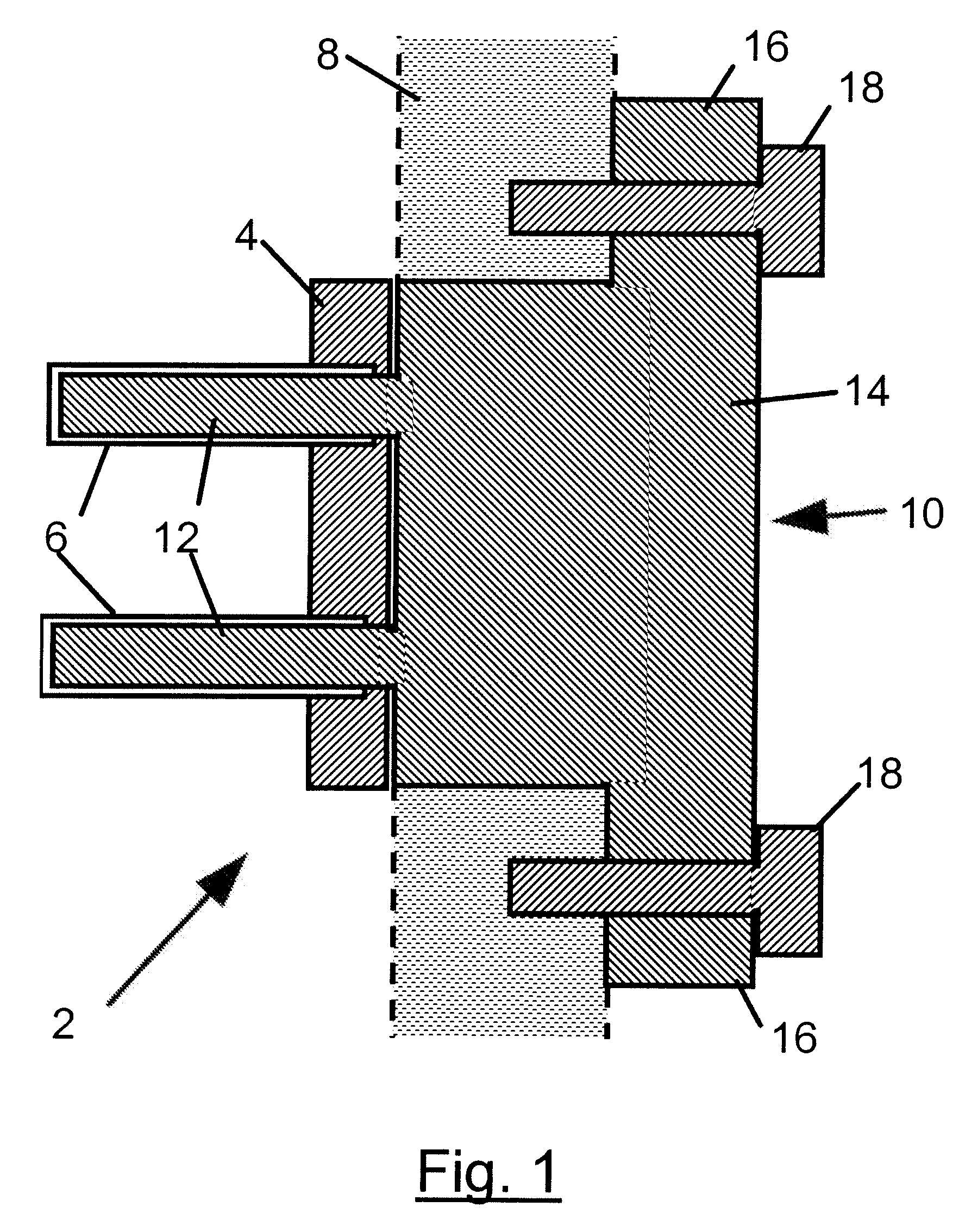
First, the dielectric measurements made using the probe 2 do not distinguish clearly between materials of different characteristics, particularly when the characteristics are similar.
Accordingly, the probe cannot be used during the initial stages of hardening.
A further disadvantage is that the construction of the holder 10 is such that it can only be used with wooden formwork or shuttering 8 in which the screws 18 can be fastened, and only with shuttering 8 of a limited range of thicknesses.
Also, there is a significant chance of leakage of the hardening material through the hole drilled in the formwork 8, around the circumference of the holder 10.

Method used


Image

  • Apparatus and method for measurement of hardenable material characteristics
  • Apparatus and method for measurement of hardenable material characteristics
  • Apparatus and method for measurement of hardenable material characteristics

Examples


Embodiment Construction

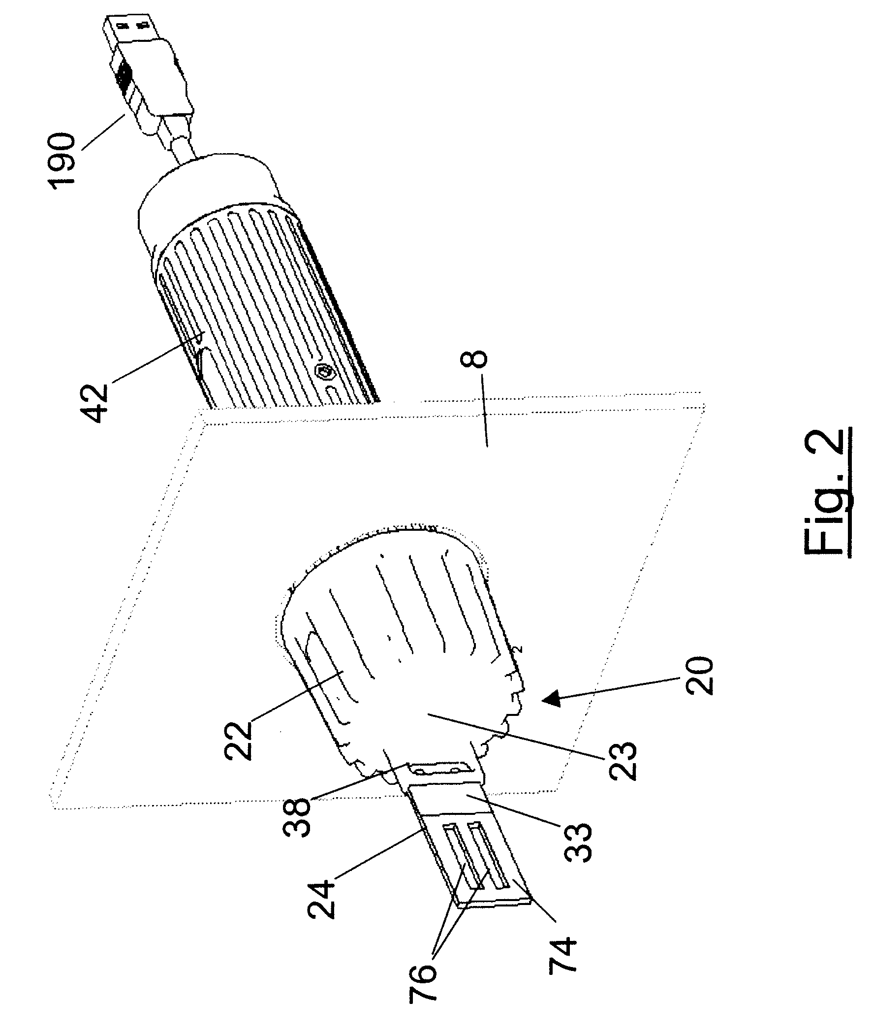
[0037]Referring to FIGS. 2 to 4, a measurement probe 20 comprises a hollow, generally cylindrical cup-shaped body 22 which is open at its proximal end and which has a closed, distal end 23 from which a sensor device 24 projects.

[0038]The probe 20 is intended to be embedded into concrete and can be supported in a number of different ways (as will be described below). In the mode of operation shown in FIGS. 2 and 4, the probe 20 is held on the inside of a mould wall formed by formwork 8, using a retainer 26 mounted on the outside of the formwork 8, but extending through an aperture in the formwork into the body 22 of the probe 20.

[0039]In the illustrated preferred embodiment, the body 22 of the probe 20 has a threaded inner cylindrical surface 28, for cooperating with the threaded outer cylindrical surface of an extension 30 of the retainer 26. At the proximal end of the cylindrical surface 28, the inner surface has a enlarged-diameter portion forming a recess surrounded by a lip 31 f...


PUM


Abstract

A probe for measuring the hardness of concrete includes a body adapted to receive a retainer such that the combined body and retainer can be held in an aperture extending through a wall of a mould for the hardenable material, with the body extending from the inside of the wall. A sensor circuit includes detector elements supported by the body and disposed when in use in the concrete, and circuit terminals which face the exterior of the mould wall when in use, and are accessible through the retainer for connection to terminals of an external instrument. Preferably, the detector elements are conductive portions of a printed circuit board forming a resonator. The instrument can operate a switch in the probe which interconnects the terminals to indicate a good connection and measures resonator impedance at multiple frequencies.

Description

RELATED APPLICATION[0001]This application claims priority of European Patent Application No. EP 06251199.3 filed Mar. 7, 2006, entitled MEASUREMENT OF HARDENABLE MATERIAL CHARACTERISTICS, which is incorporated herein in its entirety by this reference.FIELD OF THE INVENTION[0002]This invention relates to a method and apparatus for detecting a characteristic of a hardenable material. The invention is particularly, but not exclusively, applicable to detecting the hardness of a cementitious material such as concrete, but is also applicable to detecting other characteristics of a range of construction materials.BACKGROUND OF THE INVENTION[0003]It is known to provide a probe for measuring characteristics of a hardenable construction material. For example, one known system for measuring the hardness of concrete (see U.S. Pat. No. 6,023,170) uses at least two electrodes which are placed in the concrete for the purpose of measuring the dielectric characteristics of the concrete, which are re...

Claims


Application Information

Patent Timeline
IPC IPC(8): G01R31/02
CPCG01N33/383G01N27/223
Inventor ALBADRI, ALISMITH, ANDREWROGERS, PAULMALE, PETER
Owner HYDRONIX
Learn More