

Inspection method and template
- Summary
- Abstract
- Description
- Claims
- Application Information
AI Technical Summary
Benefits of technology
Problems solved by technology
Method used
Image

Examples
first embodiment
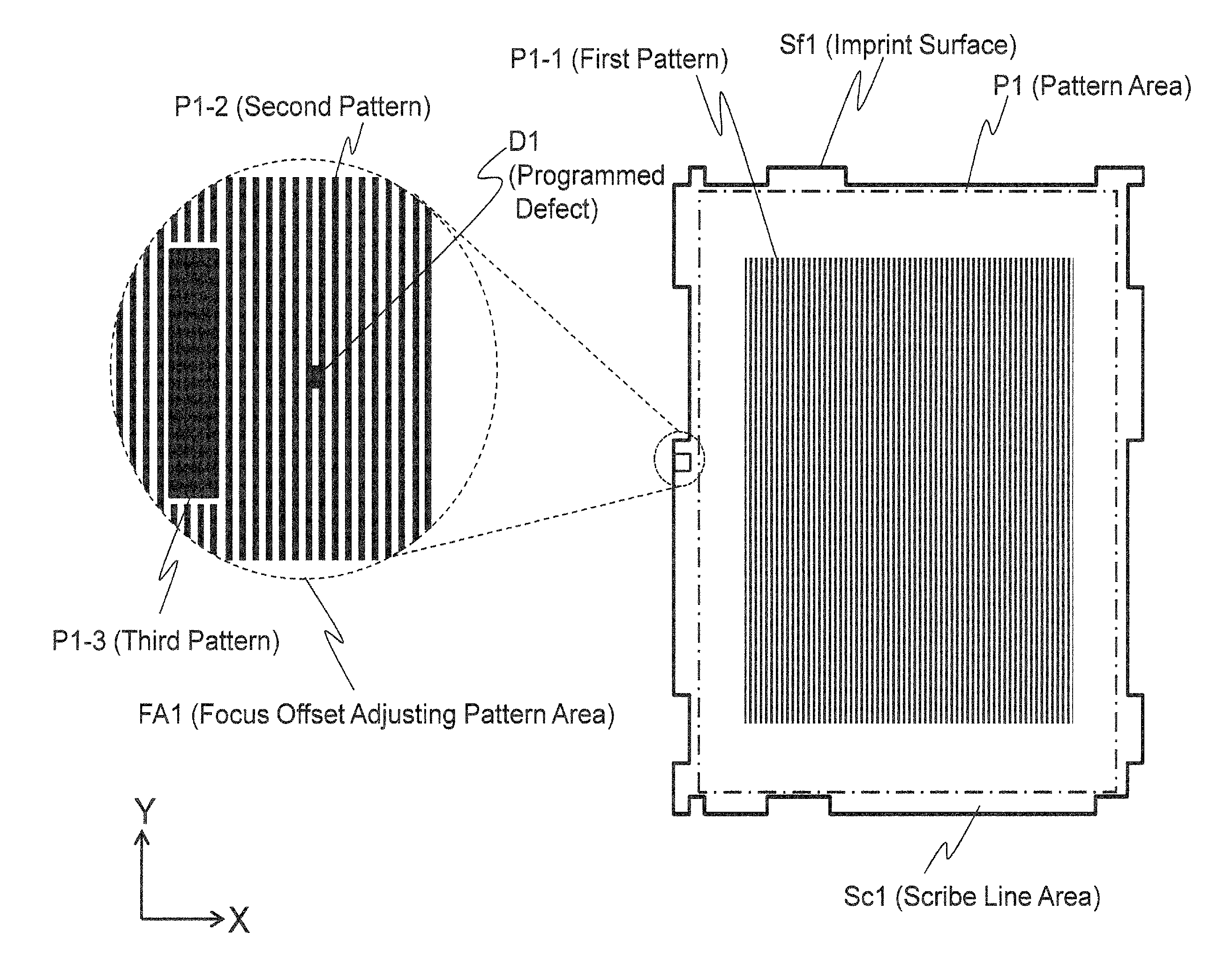
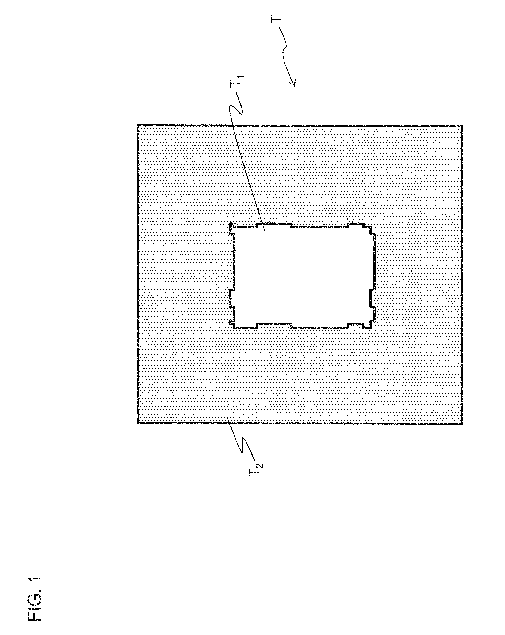
[0077]The template of the first embodiment is one in which a circuit pattern is engraved in a glass substrate, and the template has a mesa structure in which a portion corresponding to an area necessary for the imprint is left in a convex shape while a surrounding area of the portion is removed by a digging process. FIG. 1 is a plan view schematically illustrating a state in which the template is arranged on a table of the inspection apparatus. In FIG. 1, the template is designated by the numeral T, the numeral T1 corresponds to a convex portion, and the numeral T2 corresponds to the dugout portion. The convex portion T1 becomes the imprint surface.
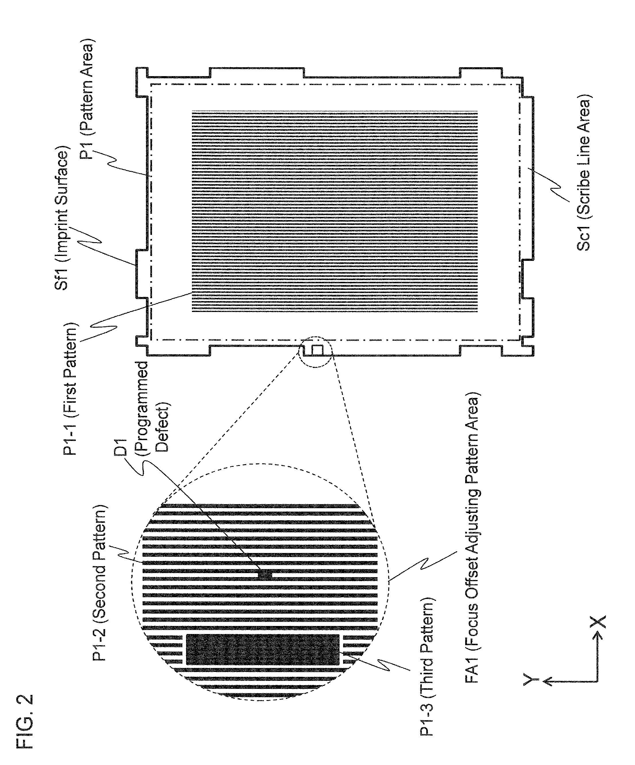
[0078]The circuit pattern is formed on the imprint surface to be imprinted to the wafer. In the inspection of the template, the circuit pattern is the inspection pattern. The circuit pattern consists of a repetitive pattern such as a line-and-space pattern or contact hole pattern, that is, a regular repetitive pattern having periodicity.
[...
second embodiment
[0191]In the first embodiment, it is mentioned that the focus offset is adjusted before the direction of the pattern to be inspected is obtained by providing the second and third patterns in the focus offset adjusting pattern area. On the other hand, in the second embodiment, the alignment mark area (the alignment mark and surrounding areas) has the function for adjusting the focus offset. In the present embodiment, the kind of alignment which is the purpose of the alignment mark is not specifically limited. That is as some examples of alignment, the position alignment between a wafer and a template, the position alignment between a lower film and upper film during the formation of multiple-layer wiring, and plate alignment during the inspection process, are all possible.
[0192]The pattern to be inspected according to the present embodiment is a circuit pattern disposed in the imprint surface of the template. The circuit pattern consists of a repetitive pattern such as a line-and-spa...
third embodiment
[0210]In the first embodiment, the second pattern in which the programmed defects are provided, and the third pattern for detecting the direction of the pattern to be inspected, are provided in the focus offset adjusting pattern area. Further, in the first embodiment, the inspection method includes a step for adjusting the focus offset value after the direction of the pattern to be inspected is obtained, and a step for determining the rotation angle of the Faraday rotator.
[0211]In the inspection method of the first embodiment, the focus offset value is adjusted so as to be the optimum focus offset value for detecting a defect by maximizing the signal-to-noise (S / N) ratio of the image signal. The rotation angle of the Faraday rotator is determined so as to remove the light-dark unevenness caused by the edge roughness.
[0212]On the other hand, in the inspection method according to the third embodiment, a new evaluation scale considering the intensity of the signal of the defect, and th...
PUM
 Abstract
Description
Claims
Application Information